 Tweet
Tweet
Originally posted by DV52
View Post
-
Got ya. I'll see what I can find next time I'm in the console 2016 GTI Performance | Pure White | JB1 | Dog Bone | Full Tint | Stop/Start Delete | Avatar by sandwg
 -
Matt: Been a while since this thread got updated, so I thought that would write to say that I'm still waiting for the second mono-oscillator to arrive. Even though I got a fast delivery service on the second chip it seems to be taking an inordinate length of time to get through our customs process . I've updated my first post to include some basic tips, but when I build the new unit, I'll also include pics about construction.Originally posted by mattaus View Post
So hang-in there and I'll let you know when I can ship-up the new device!
Cheers
Don
PS: I think that I have found an alternative method for building the device. Instead of basing the design on a delayed mono-stable oscillator, I'm experimenting with a neat little memory module that can perform the same function. It's also purchased off-the-shelf, it's physically smaller than the mono and it is completely self-contained (but it still needs the relay and the diodes for spike/noise suppression).
The memory module is fascinating in that it can be simply programmed without the need to use any other equipment. Absolutely brilliant concept (IMO) and it's so, so easy to use that even a silly old fart like me with a feeble and aging brain can understand how it works!! And it costs less than $20 AUD (plus delivery).
Anyway I'll write more about this when I get this alternative design working- but it looks very promising indeed.Last edited by DV52; 22-10-2015, 11:31 AM.Please don't PM to ask questions about coding, or vehicle repairs. The better place to deal with these matters is in the forum proper. That way you get the benefit of the wider expertise of other forum members! Thank you.Comment
-
Very interested in this. I have the same issue I want to deal with on a Porsche Boxster that this could be used for......
here's a link to some similar solution for that issue FWIW:
981 Sport Mode button hack - Page 4
May be of some assistance re VW.Comment
-
Fontana: Hello and thanks for the link.Originally posted by fontana302 View Post
Yes, I did consider using an Arduino style chip - the Digispark seems to be a form of Arduino, but with less "smarts". But I discounted this design because others would need to download the delay program for establishing T1 and T2. It became fairly obvious after starting my research that off-the-shelf devices were readily available at a reasonable cost without the need for computer based programming.
The delayed Mono stable oscillator is an analogue example of how to generate these two time segments and the memory module (which could well be based on the Digispark concept) is a digital way of achieving the same function, but without needing any external software.
My quick reading of the Porsche site suggests that the same solution could apply, but the blog is delightfully vague about the actual circuit that needs to be circumvented to enable sports mode. Do you have any information (perhaps a section of the wiring diagram) indicating exactly what the sports mode switch does (I assume the boxer has a sports mode switch)?
DonPlease don't PM to ask questions about coding, or vehicle repairs. The better place to deal with these matters is in the forum proper. That way you get the benefit of the wider expertise of other forum members! Thank you.Comment
-
Hello Don - are you able to say what the alternative method is you're working on?Originally posted by DV52 View Post
I've got my car now and the quick tests I've done, without it connected to the switch yet, seems to work well when the car is powered on /off.
So now I'm getting close to making a PCB for my version of the circuitMY21 Golf MK8 GTI | Kings Red Metallic | all options |
MY16 Golf MK7 GTI PP | White | With Leather |
MY11 Golf MK6 GTI DSG | CW | 5dr | Bi-Xenons | ACC | 18" Detroits | RNS510 with Dynaudio| RVC | MDI |Comment
-
AJW: First- congratulations on getting the new car - I know you will enjoy every minute that you drive it! Second, well done on getting your design to operate successfully. The circuit looked like it would work in theory, but it's always good when the bench-test proves what you had in your head!! I look forward to seeing pics of the constructed PCB and the installation set-up.Originally posted by AJW View Post
As for my alternative design, I've order a test unit and I'm now awaiting delivery. I'll write-up my observations when I get delivery and try it out on the work bench.
I'm even more convinced now that there are many designs that will work on this function. I was even sent the link below by a forum colleague of a commercial unit that looks like it fits across the native S/S button. But it costs 85 Euros - outrageous!!
Start-Stop-Automatic-Memory-Modul (SSAM-Modul)-
Cheers
DonLast edited by DV52; 30-10-2015, 03:58 PM. Reason: See full description of alterate design and construction in next postPlease don't PM to ask questions about coding, or vehicle repairs. The better place to deal with these matters is in the forum proper. That way you get the benefit of the wider expertise of other forum members! Thank you.Comment
-
Auto Start/Stop Kill Switch - Alternate Design
As an alternative to the Auto S/S kill switch that is described on post #1 of this thread, the following design uses a different "programmable" module that is readily available from the net. The "Multi-Functional Delay Timer" (MFDT) can be programmed to undertake 17 x different timing functions, but as used in this design, the inbuilt function #7 performs the exact timing characteristics that are described in post #1 of this thread.
The MFTD can be purchased from EBay and Amazon (see link below), or it can be obtained directly from the distributor via the last link below:
Multi-functional Delay Timer
The MFDT has 6 x wires as shown in the diagram below:As indicated, the device has the same four wires as per the original Mono (i.e. Vcc, Earth, Vout and Trigger) plus it has two additional wires that are used for programming the T1 and T2 timing periods.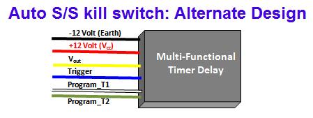
The circuit diagram for the MFTD unit is shown in the diagram below:As indicated, the connections are the same as those for the Mono except that the Trigger wire is not used and the two programming wires are not connected (these wires will be used later). Also, the "freewheeling" diode across the relay coil is not required because a diode has already been included for this purpose inside the MFDT.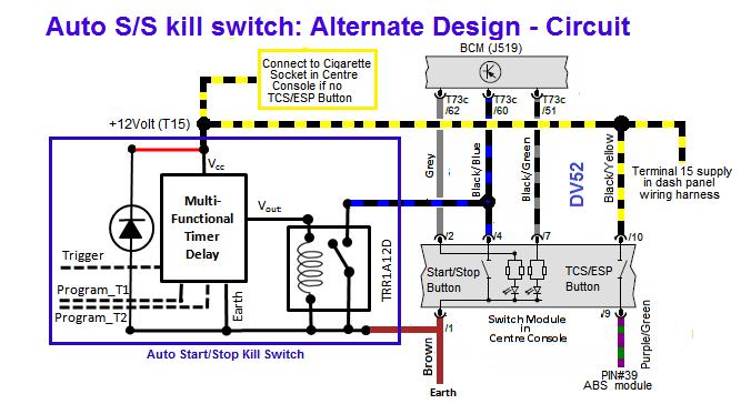
Construction- Solder the relay (all legs) and the diode onto a small piece of "Vero" board so that the components are mounted on the track side (the relay should be oriented so that "notch" in on the LHS of the board as shown in the Back-view picture below). Before mounting the relay, remember to remove a section of the track where the relay package is to be placed so that the pins on opposite sides of the relay don't short each-other.
- Place a piece of double sided tape to one of the faces on the MFDT and secure the vero board to the other side of the tape
- Solder the Red, Black and Yellow wires on the MFDT to the components on the vero board as per the circuit diagram
- Solder three wires to the vero board for the connections to be made to the centre console switch as per the circuit diagram.
- The three wires coloured White, Green and Blue should not be connected
The pictures below indicate the finished Auto S/S kill switch: Alternate design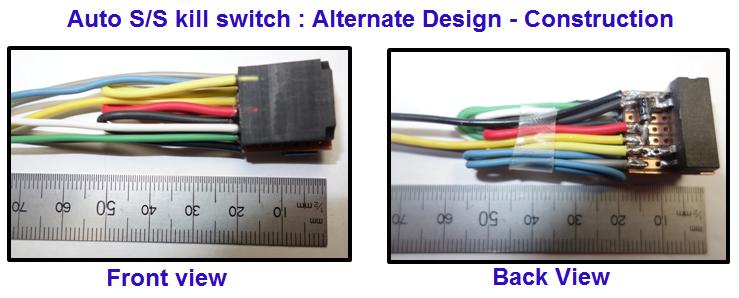 Programming Circuit
Using a test bench power supply, or a 12 Volt batttery construct the ciruit diagram below to program the Auto S/S kill switch
Connect a button style switch to each of the white and green wires as shown and connect a LED and series resistor to "see" the pulse signal.
Programming Procedure:- With the power switch off, hold down the two buttons, then turn-on the power switch and release the buttons. The LED will illuminate for 3 seconds to indicate that the device has entered the programming mode. Keep the power switch turned-on for steps 2, 3 and 4 of these procedures
- Set T1 period: Hold down the button that is connected to the white wire for about 5 seconds. Release the white wire button and the LED will extinguish
- Set T2 period: Hold down the button that is connected to the green wire for about 2 seconds. Release the green wire button and the LED will extinguish.
- Set Mode: The last step is to set the MFDT to Delayed Interval (single cycle) mode - this provides the timing sequence shown in post #1 of this thread. The code for this mode is 7. To set the mode, momentarily press and release the two buttons together - the LED will flash to indicate that you have entered mode selection. Press the white wire button seven times to set mode 7
- Turn-off the power switch - the MFDT is now programmed!
To test the correct timing periods, turn-on the power switch and observe the LED operation.
If T1, and/or T2 need to be re-adjusted, repeat the steps outlined above. (note: there is no need to complete step 4 again - once the mode is set initially, it will remain at the set number).
That's it - Remove the device from the programming circuit, remove the two buttons and secure the unused wires neatly so that they don't short against any other components. Then slip the completed Auto S/S kill switch into a piece of heat shrink tubing and install in the car.
Installation:
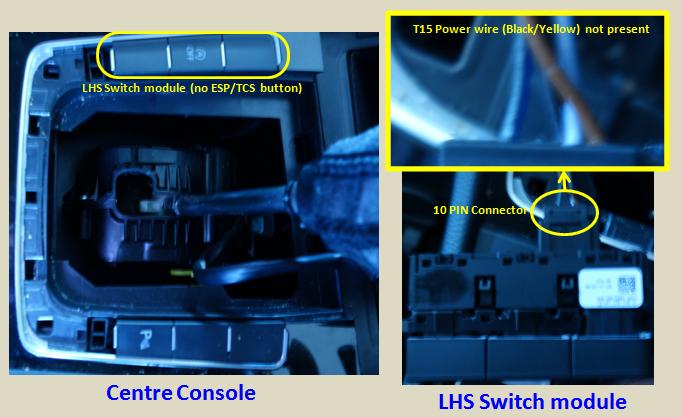
Mattaus will describe the installation of the "test device" in his mk7 which has additional buttons in the centre console, but in my MY13 model, there is only one button on either side of the gear selector lever. This means that the T15 power supply wire (Black/Yellow) is not in the wiring loom for the 10 PIN connector to the switch module.
For those in this situation, the additional T15 wire needs to be provided and I found that the most convenient method of doing this was to install a "piggy-back" fuse on fuse position #40 in the "C" fuse box (which is located behind the glove box for those cars that have the steering wheel in the correct side).
Given that I needed to work in the "C" fuse-box area anyway, and because access to the centre console is such a PITA, and because I'm still not certain that the time periods for T1 and T2 are correct (it's therefore likely that I will need to take-out and re-install the device), I decided to mount the Auto S/S Kill switch in the "C" fuse box as well (instead of the cavity in the centre console). To do this, I spliced the two wires to PIN #1 and PIN #4 on the 10 PIN connector and extended these into the "C" fuse box area.
A picture of the complete installation is shown below (note: to minimise the possibility of the device rattling, I wrapped the the completed unit in "bubble-wrap"):So far the device is working perfectly albeit, I 'm tempted to reduce T1 to about 3 seconds. I'll wait for feedback from Mattaus and AJW before making this change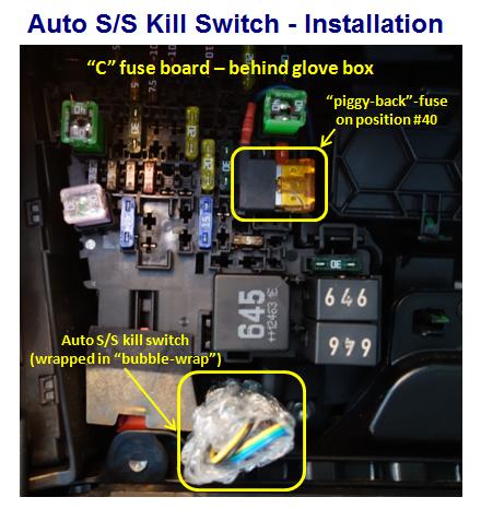
Cheers
DonLast edited by DV52; 16-04-2020, 05:06 PM.Please don't PM to ask questions about coding, or vehicle repairs. The better place to deal with these matters is in the forum proper. That way you get the benefit of the wider expertise of other forum members! Thank you.Comment
-
I'll be installing my design on the weekend - see how it goes.
I've got a temporary design on protoboard, then I'll make a PCB if it works ok.
Don - good find with that programmable module, probably would have used that if I was starting from scratch.
Do you have to tie the trigger to GND or is it OK floating?
See how my version goes if it doesn't work I might have a look at this module.
Would be nice to have the relay and module all mounted on one PCB.
Where I'm looking to mount the PCB behind the gear lever there's about 12 min thickness.MY21 Golf MK8 GTI | Kings Red Metallic | all options |
MY16 Golf MK7 GTI PP | White | With Leather |
MY11 Golf MK6 GTI DSG | CW | 5dr | Bi-Xenons | ACC | 18" Detroits | RNS510 with Dynaudio| RVC | MDI |Comment
-
AJW: I've asked this same question of the manufacture and I've yet to get a response, but I beleive that it can just be left unconnected. But you could always connect the trigger to earth if you want - it wont do any harm.Originally posted by AJW View Post
The thickness of the completed version II switch (as in my pics) is 12.5 mm (as measured with a vernier calliper) without the heat-shrink tubing, so it should fit snugly in the space behind the gear lever.
As for putting both the module and the relay/diode on the same board, this is a personal choice as well. I've kind-of done this in my approach, but I've then mounted the "vero" board to the back of the module to reduce the size of the unit (at the expense of the thickness). Choosing a bigger board makes the unit thinner at the expense of width and length! Personal preference (as I said)
Matt now has the fully constructed prototype version1 unit, so I'm hoping to get feedback shortly.
Cheers
Don
EDIT: I have now received a reply from the memory module manufacturer (thanks Slava) - his advice is that the Trigger wire should be left not connectedLast edited by DV52; 01-11-2015, 08:24 AM.Please don't PM to ask questions about coding, or vehicle repairs. The better place to deal with these matters is in the forum proper. That way you get the benefit of the wider expertise of other forum members! Thank you.Comment
-
Installed my version of the Circuit today. For those following along I'm using a NE556 + Photomos Solid state relay.
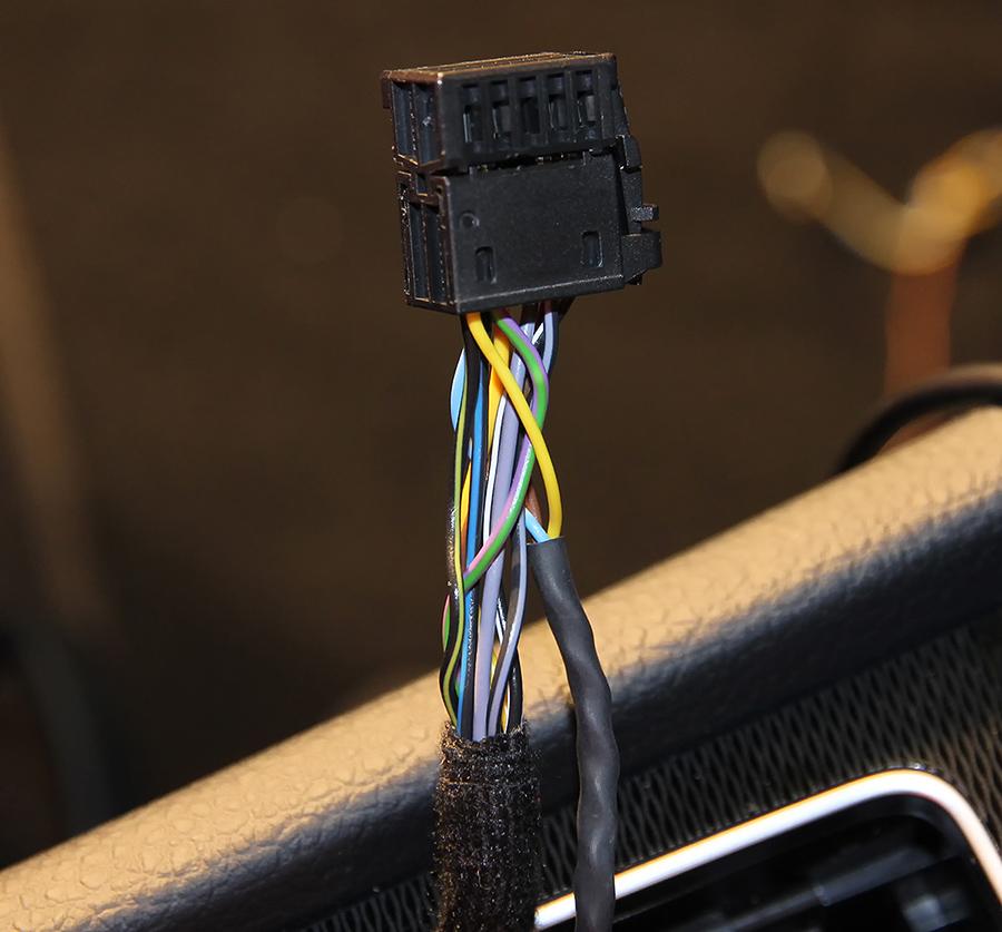
I was able to get the connector apart and remove the pins so I could solder the wires directly onto the pins.
You still need to push a metal spring in first (you can see it in the picture on the pins still in place).
There's 2 small flaps either side that stop the pin from completely coming out after you've pushed the spring tag in.
Really nice connector , Swiss made, seems to make contact in 4 places at once, easy to pull apart for a change.
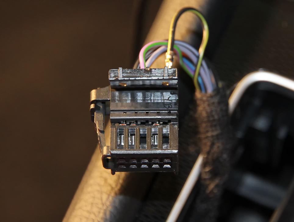
You can see it's nice and neat with the wires coming out of the connector and no wire splicing.
I made a pin header connector at the other end of the wiring loom so I could easily plug it into my PCB.
I'll heatshrink it all together when I make my PCB.
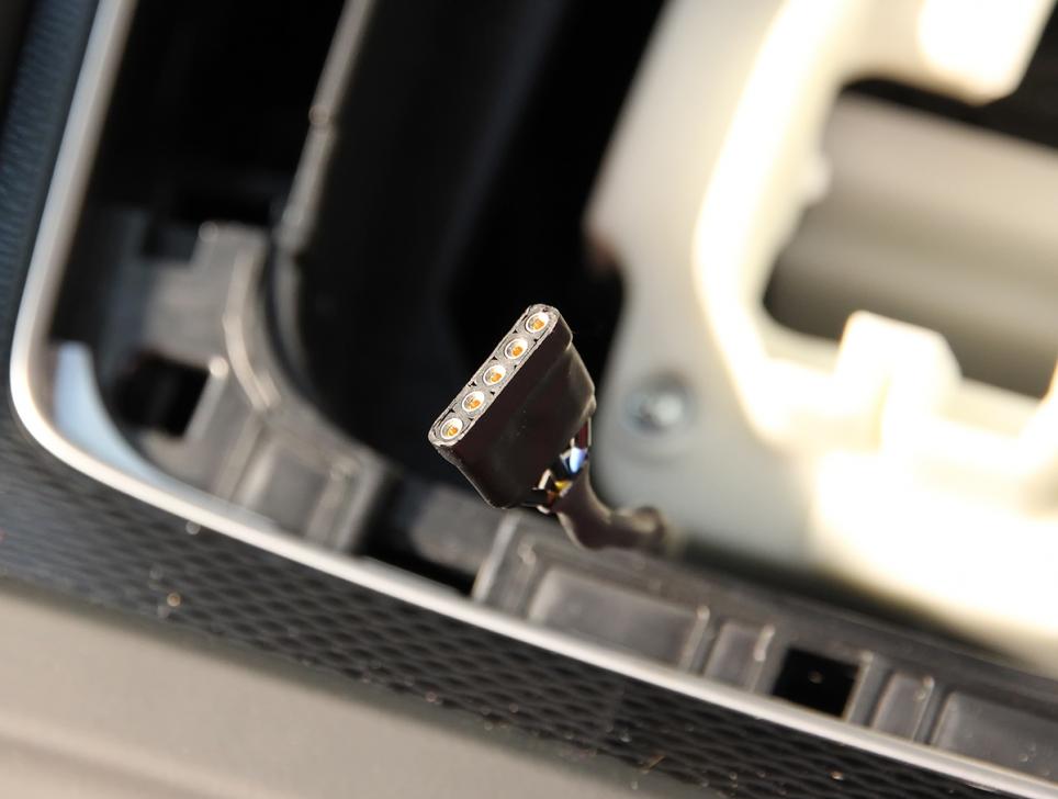
Here's my prototype PCB mounted behind the gear lever.
The SMD PCB will be about a 1/5th the size of this.

And yes it all works, I've got about a 10 second delay before it turns the Start/Stop off.
The only combination of sequences I can see where it wont work is if you:-
Start the car drive around, stop the car with the Ignition on then restart the car.
To make that work you have to start monitoring the Start/Stop LED which I think is overkill.
I'd say this simple way will cover about 90% of the operation for me.
I'll run it in the car for a while then start on my SMD PCB version.
Also forgot to add, I'm also seeing around 2vdc & about the same AC on the switch contact with the power on (Measured with Fluke 179 meter).
Doesn't seem to effect my Solid State relay operation.Last edited by AJW; 31-10-2015, 01:22 PM.MY21 Golf MK8 GTI | Kings Red Metallic | all options |
MY16 Golf MK7 GTI PP | White | With Leather |
MY11 Golf MK6 GTI DSG | CW | 5dr | Bi-Xenons | ACC | 18" Detroits | RNS510 with Dynaudio| RVC | MDI |Comment
-
That's awesome AJW!
I plan on installing my test unit tomorrow. I was going to do what you did with the plug. Don was kind enough to also include a header plug for me so that'll make things easier. Good place to mount the unit too; mine should fit in the same spot. The ultimate solution would be to run the header outside of the console so that the S/S device could be removed without tearing the dash apart. There are a few spots that this could work but I'll look in more depth tomorrow.
So is there room inside the connector to actually run two wires to the one pin? Looks like there is from your photo so that's great.
Did you have any troubles getting your console apart?2016 GTI Performance | Pure White | JB1 | Dog Bone | Full Tint | Stop/Start Delete | Avatar by sandwgComment
-
The wire I used was reasonably small so I was able to fit it in the plug with the original wire - slightly thinner than the car wiring.
Console was pretty easy to get apart , this was my second time.
I think the hardest part is removing the rear "U" shape trim - just used a screw driver and went along one side to the other.
Also if you're soldering in the car I always cover everything in towels, having solder splats on the dash or leather isn't a good look.
Plus I always keep tools in the foot well so there's no chance sitting on some tweezers and having them go into your seat.MY21 Golf MK8 GTI | Kings Red Metallic | all options |
MY16 Golf MK7 GTI PP | White | With Leather |
MY11 Golf MK6 GTI DSG | CW | 5dr | Bi-Xenons | ACC | 18" Detroits | RNS510 with Dynaudio| RVC | MDI |Comment
-
AJW and Matt: I guess the old adage about life being hard for the wicked is certainly true in my case!!
I just had a rummage around in the centre console on my car and I have to say that it's a little different to the pics that you have both put-up (thanks for doing this -by the way)
My car doesn't have the fancy fittings of your later models. On my MY13 car, there is only one switch on either side of the gear lever (i.e. the S/S disable switch on the LHS & the Park assist button on the RHS. As I feared in a previous post, my quick look this afternoon confirmed that there is no Black/Yellow wire to be seen anywhere in the switch loom, or in the cavity around the gear selector module - bummer!! (see pics below).
I can see the cables that head-off in the direction of the ciggy socket, but they are firmly attached to the bottom of the console assembly, so hooking the loom and raising it to the top of the console isn't practical.
Had a go at trying to get to the ciggy socket connector, but access looks problematic unless I dismantle the entire centre console. I suspect that a better solution might be to run a cable to the fuse panel behind the glove-box (VW call this the "C" fuse box). But it needs further thought.
Anyhow, I'm glad that the install will be easier for the "young blokes" - LOL
Cheers
Don
PS: AJW _ I agree that the hardest part of the process is removing the plastic "c" section - Like you I managed it with a small flat-sided screwdriver, a deft touch and a lot of patience!
 Last edited by DV52; 31-10-2015, 05:04 PM.Please don't PM to ask questions about coding, or vehicle repairs. The better place to deal with these matters is in the forum proper. That way you get the benefit of the wider expertise of other forum members! Thank you.
Comment
Comment