 Tweet
Tweet
OK, so needing to kill time before I headed off to the gym I did go and have a fiddle (stop sniggering in the back).
I'll take better photos (during the day would be a good start) when I do an actual full install guide.
The good news! The pins are marked (forgive the ****ty camera):

And low-and-behold there is a yellow and black wire connected to socket 10. I was unable to test the voltage on this because I did not have a lead for my DMM small enough to fit anything. I'll have to raid my electronics box for something that will work.
Now the switch cluster itself looks like this:

I'm hoping Don's plan involves wiring into the plug that goes into the bottom of the 3 switch cluster rather than the actual S/S switch itself, because bugger me if I could get the cluster apart. I'm sure it's possible but this stuff is fragile and I do not want to snap something 10 day old car just yet!
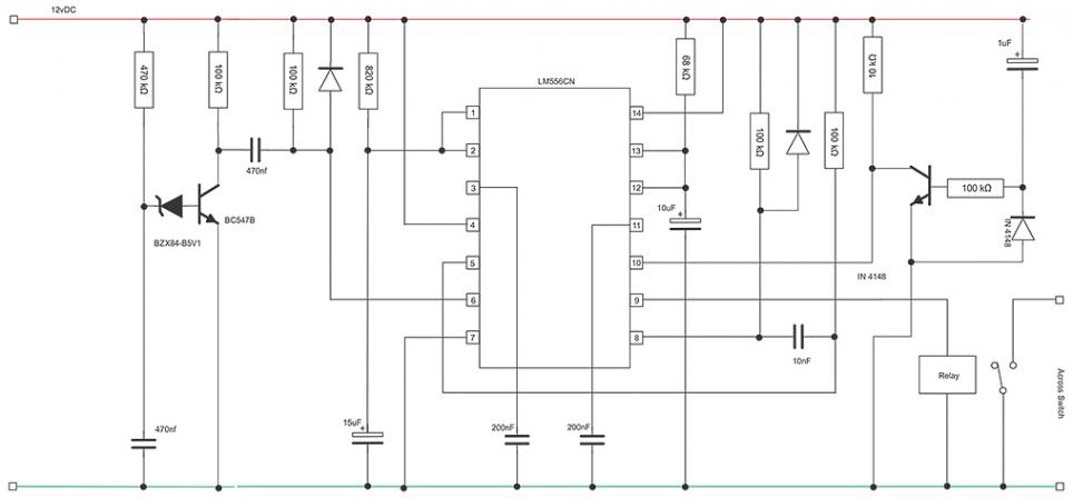
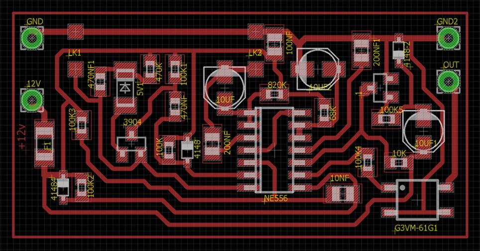
My thoughts are that there will be no need to pull the switch assembly apart because one of those 10 sockets on the wire harness will surely be responsible for sending the ground signal back to the brains? It's likely obvious from the diagram's Don has already included but I'm in a hurry and just wanted to get this up before I had to leave for a few hours. Hopefully the brains trust will have answers for me when I come back
Sorry if this doesn't really tell us anything helpful!
- Matt
I'll take better photos (during the day would be a good start) when I do an actual full install guide.
The good news! The pins are marked (forgive the ****ty camera):
And low-and-behold there is a yellow and black wire connected to socket 10. I was unable to test the voltage on this because I did not have a lead for my DMM small enough to fit anything. I'll have to raid my electronics box for something that will work.
Now the switch cluster itself looks like this:
I'm hoping Don's plan involves wiring into the plug that goes into the bottom of the 3 switch cluster rather than the actual S/S switch itself, because bugger me if I could get the cluster apart. I'm sure it's possible but this stuff is fragile and I do not want to snap something 10 day old car just yet!
My thoughts are that there will be no need to pull the switch assembly apart because one of those 10 sockets on the wire harness will surely be responsible for sending the ground signal back to the brains? It's likely obvious from the diagram's Don has already included but I'm in a hurry and just wanted to get this up before I had to leave for a few hours. Hopefully the brains trust will have answers for me when I come back
Sorry if this doesn't really tell us anything helpful!
- Matt
Comment