 Tweet
Tweet
Originally posted by wookie_666
View Post
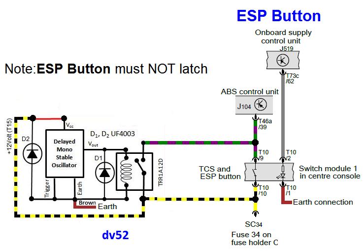
My only concern is whether the ESC switch is the latching type: does the disable/enable function work on the leading/trailing edge of the +12 Volt source like the SS Switch, or does it need the +12 Volt to remain applied?
When the ESC switch is pressed and then released, does the switch return to the normal position, or does it latch in the pressed state (and then return when pressed again)?
Assuming the answer to my question above is NO - here's how to modify my switch to operate as an Auto ESC Kill Switch:
Don
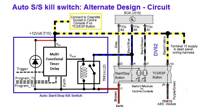
PS: My guess when you used the multi-meter to test continuity is that the ABS module saw the internal battery in the multi-meter as a surrogate for the +12 Volt supply from SC34 in my picture. As you probably already know, continuity testing involves measuring the electrical current from a known battery voltage internal to the multi-meter


Comment