G-8VXWWTRHPN Golf mk7: Auto Start/Stop disable switch - who wants to help? - VWWatercooled Australia

Announcement

Collapse
1 of 2 < >

Email Notifications Failing (mostly Telstra)

Hello everyone. Seems there is an issue with Telstra (possible others) blocking email from our server. If you are trying to sign up I would suggest a different email if possible. If you're trying to reset your password and it fails please use the Contact Us page:
2 of 2 < >

Welcome to the new look VWWatercooled

After much work and little sleep there is a new version of the forums running on more powerful and recent hardware as well as an upgraded software platform.

Things are mostly the same, but some things are a little different. We will be learning together, so please post questions (and answers if you've worked things out) in the help thread.

The new forum software is an upgraded version of what came before, it's mostly the same but also a little different. Hopefully easier to use and more stable than before. We are learning together here, so please be patient. If you have questions, please post them here. If you have worked something out and can provide an answer,
See more
See less

Golf mk7: Auto Start/Stop disable switch - who wants to help?

Collapse
X
 
  • Filter
  • Time
  • Show
Clear All
new posts

  • Originally posted by wookie_666 View Post
    So i ended up making one of these yesterday

    Using an arduino pro nano
    A logic level relay (which is basically a 5v relay)
    a Polulu voltage regulator

    I mounted it all to a perf board, did the 3 connections (+ve, -ve, and sensor), and mounted it in behind the shifter,
    Connect it to the 3 wires noted on the page 1 and page 6 of this thread.

    It works flawlessly. Thanks for all who are involved.

    (ps, arduino is probably overkill, but the ability to be able to code it to do exactly what i want makes it much easier. And the pro nano isn't much bigger than some of the other modules i have seen in this thread).
    wookie: well done! So why didn't VW make this simple modification at the factory? Not sure if you read my arduino version of the Auto SS kill switch earlier in this thread. I used a Digispark which has an AT-tiny version of Arduino.


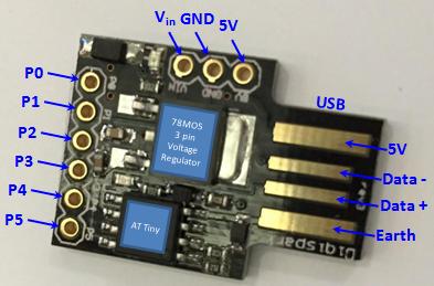
    I chose the Digispark because it already has a (simple) 3 x pin voltage regulator mounted on the shield. Just to jaz-up the design, I made a closed-loop design the confirms the status of the SS-off LED inside the console switch.

    Anyhow, as you say- the beauty of the adruino "over-kill" is its flexibility and I suspect that your code was less than 10 lines. At the time that I designed my version of the switch, there was only the Digispark, but now there is a Digispark Pro which has an EEPROM fitted. As you will doubtless know, the advantage of the EEPROM is that the switch can remember its own state at the previous ignition cycle.

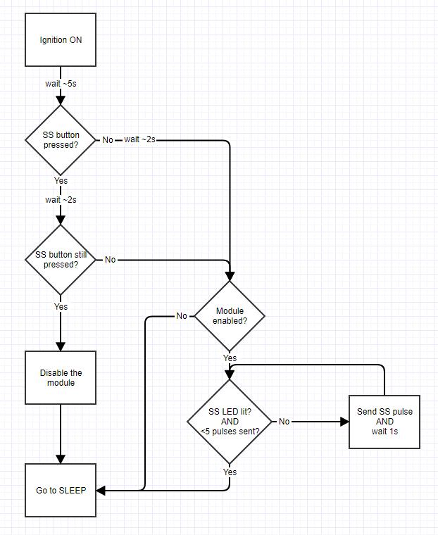
    If you are the type that likes to "embellish", try changing the code so that a long press of the SS console button when the ignition is switched-on disengages the Auto kill switch entirely (and vica-versa). This can be useful when you take your car for a service. I now tell the service manager that the switch is fitted so that he doesn't try to fault find the SS behavior in my car - so a disabling facility is useful!

    I have an intention to do this on my arduino version when I get the time!

    Don
    Last edited by DV52; 30-10-2017, 08:33 AM.
    Please don't PM to ask questions about coding, or vehicle repairs. The better place to deal with these matters is in the forum proper. That way you get the benefit of the wider expertise of other forum members! Thank you.

    Comment


    • Excellent,

      Thanks for the reply Don

      I had a chat with a workmate today and he mentioned the same thing about long press to disable/enable. And I thought to myself what would work, you have just answered my question.

      So far, i used the arduino as its what i had lying around, and the polulu voltage reg was also part of a redundant pcb i had too.

      I have mistakenly wired the power to the wire that turns the white light on and off with the headlights, so it was funny realising today why it wouldn't work when i started the car outside, and it was because the headlights didn't turn on. I couldn't get a constant 12v from the black/yellow wire, but i probably rushed, or wasn't checking properly.

      Regarding my code Im using one pin out (2), delay for 2 seconds, High for 1 second then Low indefinitely. So the code was very simple.

      Just wanted to say thanks for the research put into this, Once i had my head around it, its brilliant. I was also weary of hacking into my 7 day old wolfs wagon.

      Cheers.

      Comment


      • For the life of me, i cant think of how to sense if the button is pressed, The only thing i can think of is connecting an I/O of the arduino to the black/blue wire (which usually runs about 2v when not pressed.) The arduino would recognize this voltage and realise its not pressed. when the button is pressed, the black/blue is grounded, meaning the arduino would recognize zero voltage and know its pressed.

        Would I connect that Black/blue to an analog pin or digital pin. Im not sure if that voltage is AC Or DC as i have read before in this thread something about AC voltage.

        Comment


        • Originally posted by wookie_666 View Post
          For the life of me, i cant think of how to sense if the button is pressed, The only thing i can think of is connecting an I/O of the arduino to the black/blue wire (which usually runs about 2v when not pressed.) The arduino would recognize this voltage and realise its not pressed. when the button is pressed, the black/blue is grounded, meaning the arduino would recognize zero voltage and know its pressed.

          Would I connect that Black/blue to an analog pin or digital pin. Im not sure if that voltage is AC Or DC as i have read before in this thread something about AC voltage.
          wookie: hm............... very good question indeed! Why not do as you suggest but make the black/blue wire perform both input and output functions - connected to separate ports. I have always preferred to electrically insulate the BCM away from any add-on new circuitry, so an opto-isolator seems ideal. perhaps something like this:


          So- the black/blue wire becomes an input (via the opto-isolator) to P3 for the purposes of sensing whether the console switch is pressed and the black/blue wire also becomes an output (via the other opto) via P2 for the sending the actual SS kill signal.

          I've deliberately tied P3 to the 5 volt rail (via the 4.7K resistor), so this input has a digital state (not analogue). Also I'm guessing about the 1 K current limiting resistor on the input of the opto-coupler. I'm not sure about the capability of BCM pin to source 14 millamps as a parasitic current for the LED in the opto - so you might need to use a different resistor (again, I'm not sure). I'm assuming that the BCM pin is an open-collector circuit. I'm not sure about your 2 Volt reference, but I haven't actually measured the open switch voltage on pin #60. If it's really 2 volts, then you might need to consider an ultra-low voltage switch. The in-line diode simply stops P2 from turning-on the P3 opto (P2's only role is to ground the blue/black wire when the SS kill pulse is sent).

          Of course you can arrange your program commands anyway that you want, but I suspect that the first part of the routine will be to look at the state of P3 immediately after ignition switch-on:
          • if P3 is HIGH, the button isn't pressed and the normal Kill pulse can be initiated.
          • If P3 is LOW, the kill switch sub-routine is bypassed and a flag is set to indicate that the device is in disabling mode.
          • Of course if the disabling flag is already set and P3 is LOW, then the pressed button means that you want to re-enable the SS kill function - hope this makes sense!
          • Probably wise to make sure that the button is pressed for at least a certain amount of time (perhaps 5 seconds) to make sure that the sub-routine doesn't catch an inadvertent button press.


          Good luck - you will probably be the first to make one of these!!
          Don
          Last edited by DV52; 30-10-2017, 05:30 PM.
          Please don't PM to ask questions about coding, or vehicle repairs. The better place to deal with these matters is in the forum proper. That way you get the benefit of the wider expertise of other forum members! Thank you.

          Comment


          • Damn Don, youve lost me mate.

            But I think i get the gyst of it.

            When you say optocoupler, what module are you thinking, my current setup is using a logic level relay from jaycar to do the switching, but obviously 2v from black/blue is not enough for that, I guess i could either use an op-amp, or a different relay. Or did you have something else in mind.

            Regarding the 1k resistor, could you please explain why thats needed. Couldn't i just leave it out.

            with the coding, ill have the loop check for p3 being high/low, and then ill run different functions when it changes.

            Comment


            • ^^^ OK - 2 Volts will be a problem with my design.

              The "Opto-coupler" is the 4N28 in my circuit (it's a gallium arsenide infrared LED, which is "optically coupled" to a monolithic silicon phototransistor).

              You can't remove the 1K resistor because LEDs are current devices, they generate heat which increases current, which increases heat - result is thermal runaway and destruction!! Here's the spec for the electrical characteristics of the LED in the opto-coupler (it's from the 4N28 datasheet):


              If the 1K resistor is removed, the full 2Volts will be applied across the led. The chart says, that the LED will readily take about 500 mA with that level of forward voltage - if indeed the BCM pin could supply this level of amps. More likely, I suspect that something inside the BCM would saturate to limit current flow - but with only 2 Volts, it's entirely unknown if the LED in the opto-coupler would illuminate sufficiently to turn-on the photo transistor.

              The real problem is that we just don't know the electrical capabilities of pin #60 (socket C) on the BCM as a source of supply. This pin was designed by VW to be an input source- not to be an output source for an external device. So the trick is to make sure that any parasitic current drain for P3 on the Digispark is not seen by the BCM as being too much load.

              My original design was very conservative and I tried to totally isolate my add-on circuit from the inner workings of the BCM.

              As I said, with 2 volts, I suspect that some form of ultra-low volt switch is needed. Perhaps you could consider a FET switch since these require very little drive current and they can be designed to switch ON/OFF at low voltages.

              Don
              Please don't PM to ask questions about coding, or vehicle repairs. The better place to deal with these matters is in the forum proper. That way you get the benefit of the wider expertise of other forum members! Thank you.

              Comment


              • Thanks for the reply don.

                I have since decided against the press and hold to switch on/off the killswitch. I mean, the reason people put these in is to turn the switch off every time. If you were worried when getting it serviced, its a 5 second thing to unclip the surround, and unplug the killswitch.

                Comment


                • Hi guys!
                  I made my own clone with digispark and 3 optocouplers for reading the button state back.
                  If it works (I will be testing it this week) and there is anybody that would want i can produce the diagrams, but it's a simple permutation of Don's circuit.

                  I will publish my code now though, in case anyone is interested. It does exactly what Don suggested a couple of posts ago (is able to disable the system if you keep the SS button pressed when switching the ignition on and waiting for about 8-10 seconds). It also should draw less current from the source, but it should not matter it is just is something 'for free'.

                  PSA: The pinouts in the code are different than what the Don's circuits had, so you would need to take this into account when using the code.

                  Code:
                  #include <avr/interrupt.h>
                  #include <avr/power.h>
                  #include <avr/sleep.h>
                  #include <avr/eeprom.h>
                  #include <avr/wdt.h>
                  
                  const byte ENABLED_BYTE = 0x55;
                  const byte DISABLED_BYTE = 0xAA;
                  
                  const byte MAX_PULSES = 3;
                  
                  const byte SS_SWITCH_OUT = 0; // opto for controlling the SS state
                  const byte DBG_LED_OUT = 1; // debug led
                  const byte SS_SWITCH_IN = 2; // opto for reading the SS state
                  const byte SS_LED_IN = 4; // opto for reading the SS off led state
                  
                  void setup() {
                    // I/O modes
                    pinMode(SS_SWITCH_OUT, OUTPUT);
                    pinMode(DBG_LED_OUT, OUTPUT);
                    pinMode(SS_SWITCH_IN, INPUT);
                    pinMode(3, INPUT); // unused
                    pinMode(SS_LED_IN, INPUT);
                  
                    digitalWrite(SS_SWITCH_OUT, LOW);
                    digitalWrite(DBG_LED_OUT, LOW);
                    digitalWrite(SS_SWITCH_IN, LOW);
                    digitalWrite(3, HIGH); // unused, enable pullup to reduce floating pins
                    digitalWrite(SS_LED_IN, LOW);
                  
                    light(LOW);
                  
                    // disable unused peripherals
                    power_timer0_disable();
                    power_usi_disable();
                    power_adc_disable();
                  
                    ADCSRA = 0;
                  
                    // maximum sleep mode
                    set_sleep_mode(SLEEP_MODE_PWR_DOWN);
                  }
                  
                  void loop() {
                    // (boot loader takes ~5s)
                    
                    // read persistend enabled state
                    byte enabled = (eeprom_read_byte(0x0000) != DISABLED_BYTE); //(!= DISABLED_BYTE, since the EEPROM is initialized as 0xFF and we want this to mean ENABLED also)
                  
                    // read the button state 
                    byte ssPressed = digitalRead(SS_SWITCH_IN);
                    if (ssPressed) {
                      // (blinks with led will delay by an additional ~2560ms)
                      blink(1);
                      blink(1);
                    }
                  
                    // after waiting reread the button state again - if it is still pressed, then swap the disabled info
                    if (ssPressed && digitalRead(SS_SWITCH_IN)) {
                      blink(8);
                  
                      enabled = !enabled;
                  
                      // persist
                      eeprom_write_byte(0x0000, enabled ? ENABLED_BYTE : DISABLED_BYTE);
                    }
                  
                    if (enabled) {
                      blink(2); // blink 2 times to mark enabled
                     
                      byte counter = 0;
                      
                      while (counter++ < MAX_PULSES && digitalRead(SS_LED_IN) == HIGH) {
                        blink(1); // blink once for every retry
                    
                        digitalWrite(SS_SWITCH_OUT, HIGH);
                        delay(1024);
                        digitalWrite(SS_SWITCH_OUT, LOW);
                        delay(512);
                      }
                    }
                  
                    blink(3); // blink 3 times as a bye bye
                  
                    // disable everything else, for minimal power consumption
                    power_all_disable();
                    power_timer1_disable();
                    wdt_disable();
                    noInterrupts();
                  
                    while(1) {
                      sleep_enable();
                      sleep_mode();
                  
                      // should not happen
                  
                      sleep_disable();
                    }
                  }
                  
                  volatile byte currentState = LOW;
                  void blink(int times) {
                    while(times--) {
                      digitalWrite(DBG_LED_OUT, LOW);
                      delay(128);
                      digitalWrite(DBG_LED_OUT, HIGH);
                      delay(128);
                      digitalWrite(DBG_LED_OUT, LOW);
                    }
                  
                    delay(1024);
                    digitalWrite(DBG_LED_OUT, currentState);
                  }
                  
                  void light(byte state) {
                    currentState = state;
                    
                    digitalWrite(DBG_LED_OUT, currentState);
                  }

                  Comment


                  • Hi there!
                    First of all, thank you very much Don for the circuit and other support on the forums!

                    I have created my own version of the circuit (this is how I like to learn new things, and I just needed to understand it first). I also wanted the disabling functionality when going to the dealer, so I would have less explaining to do and I am quite lazy so I did not want to disconnect the module every time like wookie_666 .

                    If anyone could verify my circuit, before I stick it into my car that would be great (I am not an EE and this is my first time making a circuit)

                    I had changed the pinout, so the Don's circuit translates to this one as follows:
                    P3 is now P0
                    P2 is now P4

                    The P0 pin is now sensing the SS switch state using a third optocoupler.

                    I also have un-soldered the power led from the digispark and currently the peak current while the circuit is working is below 45mA and it drops to ~8-5mA while in the sleep state (not that it matters really).

                    Since the code below enables the internal pull-ups on the unused pins, do not solder the unused pins to ground, since they will be high and you could damage your chip.

                    Here is the code:
                    Code:
                    #include <avr/power.h>
                    #include <avr/sleep.h>
                    #include <avr/eeprom.h>
                    #include <avr/wdt.h>
                    
                    const byte MAX_PULSES = 5;
                    
                    const byte SS_LED_IN = 0; // P3 -> P0
                    const byte DBG_LED_OUT = 1;
                    const byte SS_SWITCH_IN = 2;
                    const byte SS_SWITCH_OUT = 4; // P2 -> P4
                    const byte UNUSED_0 = 3;
                    const byte UNUSED_1 = 5;
                    
                    const byte ENABLED_BYTE = 0x55;
                    const byte DISABLED_BYTE = 0xAA;
                    
                     void setup() {
                      // I/O modes
                      pinMode(SS_SWITCH_OUT, OUTPUT);
                      pinMode(DBG_LED_OUT, OUTPUT);
                      pinMode(SS_SWITCH_IN, INPUT);
                      pinMode(SS_LED_IN, INPUT);
                      pinMode(UNUSED_0, INPUT); // unused
                      pinMode(UNUSED_1, INPUT); // unused
                    
                      // I/O states
                      digitalWrite(SS_SWITCH_OUT, LOW);
                      digitalWrite(DBG_LED_OUT, LOW);
                      digitalWrite(SS_SWITCH_IN, LOW);
                      digitalWrite(SS_LED_IN, LOW);
                      digitalWrite(UNUSED_0, HIGH); // unused
                      digitalWrite(UNUSED_1, HIGH); // unused
                    
                      light(LOW);
                    
                      // disable unused peripherals (timer1 is required for delay)
                      power_timer0_disable();
                      power_usi_disable();
                      power_adc_disable();
                    
                      ADCSRA = 0;
                    
                      // maximum sleep mode
                      set_sleep_mode(SLEEP_MODE_PWR_DOWN);
                    }
                    
                    void loop() {
                      // boot loader takes ~5s
                    
                      // read persistend enabled state
                      byte enabled = (eeprom_read_byte(0x0000) != DISABLED_BYTE); // treat everything not equal to DISABLED_BYTE as enabled
                    
                      // read the button state 
                      byte ssPressed = digitalRead(SS_SWITCH_IN);
                      if (ssPressed) {
                        // blinks with led will delay by an additional ~1s each
                        blink(1);
                        blink(1);
                      }
                    
                      // after waiting reread the button state - if it is still pressed, then swap the disabled info
                      if (ssPressed && digitalRead(SS_SWITCH_IN)) {
                        blink(2);
                    
                        enabled = !enabled;
                    
                        // save to eeprom
                        eeprom_write_byte(0x0000, enabled ? ENABLED_BYTE : DISABLED_BYTE);
                      } else if (enabled) {
                        byte counter = 0;
                    
                        while (counter++ < MAX_PULSES && digitalRead(SS_LED_IN) == HIGH) {
                          blink(1); // blink once for every retry
                      
                          digitalWrite(SS_SWITCH_OUT, HIGH);
                          delay(1024);
                          digitalWrite(SS_SWITCH_OUT, LOW);
                        }
                      }
                    
                      blink(3); // blink 3 times as a bye bye
                    
                      // disable everything else, for minimal power consumption
                      power_all_disable();
                      power_timer1_disable();
                      wdt_disable();
                      noInterrupts();
                    
                      sleep_enable();
                      while(1) {
                        sleep_mode();
                    
                        // should not happen
                      }
                    }
                    
                    volatile byte currentState = LOW;
                    
                    // blinks n-times, and delays by n*192ms + 832ms, eg. 1 blink = 1024ms, 2 blinks = 1216ms
                    // after blinking leaves the LED in the same state it was in (currentState)
                    void blink(int times) {
                      while(times--) {
                        digitalWrite(DBG_LED_OUT, LOW);
                        delay(96);
                        digitalWrite(DBG_LED_OUT, HIGH);
                        delay(96);
                        digitalWrite(DBG_LED_OUT, LOW);
                      }
                    
                      delay(832);
                      digitalWrite(DBG_LED_OUT, currentState);
                    }
                    
                    // changes the state of the LED
                    void light(byte state) {
                      currentState = state;
                    
                      digitalWrite(DBG_LED_OUT, currentState);
                    }
                    The simplified flow diagram:
                    (the above picture has an error, it should be SS LED lit? OR <5 pulses sent?)

                    And the schematics:


                    And the finished product (need to clean it up and isolate it):

                    Comment


                    • Hi guys,
                      I am writing this third time, since I failed to see the big notice above about the requirement to post in the newbies corner first

                      I have created my own version of the circuit (since this is the way a learn new things), that has the disabling capability for the module without the need to remove it before visiting the dealership (I do not like to take apart the interior). The idea is to keep the SS switch pressed for about 8 seconds after switching the ignition on.

                      I changed the pinouts, so:
                      P2 is now P4
                      P3 is now P0

                      and P2 is configured (using a third optocoupler) to sense the SS state for disabling purposes (of the module).

                      If anyone could verify my circuit before I stuck it into my car and break something since I am an amateur, not an EE and this is my first circuit.

                      Click image for larger version

Name:	flow.png
Views:	1
Size:	28.4 KB
ID:	1829568
                      (there is an error instead of SS LED is lit? AND <5 pulses sent? it should be: SS LED list? OR <5 pulses sent? also not disable module, but disable or enable module)

                      Schematic:
                      Click image for larger version

Name:	ssss.sch.png
Views:	1
Size:	107.8 KB
ID:	1829569

                      And the final build that still needs to be cleaned up and isolated:
                      Click image for larger version

Name:	fin.jpg
Views:	1
Size:	102.8 KB
ID:	1829570

                      And the code (take care, since pullups are enabled on the unused pins so do not short them to ground):
                      Code:
                      #include <avr/power.h>
                      #include <avr/sleep.h>
                      #include <avr/eeprom.h>
                      #include <avr/wdt.h>
                      
                      const byte MAX_PULSES = 5;
                      
                      const byte SS_LED_IN = 0; // P3 -> P0
                      const byte DBG_LED_OUT = 1;
                      const byte SS_SWITCH_IN = 2;
                      const byte SS_SWITCH_OUT = 4; // P2 -> P4
                      const byte UNUSED_0 = 3;
                      const byte UNUSED_1 = 5;
                      
                      const byte ENABLED_BYTE = 0x55;
                      const byte DISABLED_BYTE = 0xAA;
                      
                      void setup() {
                        // I/O modes
                        pinMode(SS_SWITCH_OUT, OUTPUT);
                        pinMode(DBG_LED_OUT, OUTPUT);
                        pinMode(SS_SWITCH_IN, INPUT);
                        pinMode(SS_LED_IN, INPUT);
                        pinMode(UNUSED_0, INPUT); // unused
                        pinMode(UNUSED_1, INPUT); // unused
                      
                        // I/O states
                        digitalWrite(SS_SWITCH_OUT, LOW);
                        digitalWrite(DBG_LED_OUT, LOW);
                        digitalWrite(SS_SWITCH_IN, LOW);
                        digitalWrite(SS_LED_IN, LOW);
                        digitalWrite(UNUSED_0, HIGH); // unused
                        digitalWrite(UNUSED_1, HIGH); // unused
                      
                        light(LOW);
                      
                        // disable unused peripherals (timer1 is required for delay)
                        power_timer0_disable();
                        power_usi_disable();
                        power_adc_disable();
                      
                        ADCSRA = 0;
                      
                        // maximum sleep mode
                        set_sleep_mode(SLEEP_MODE_PWR_DOWN);
                      }
                      
                      void loop() {
                        // boot loader takes ~5s
                      
                        // read persistend enabled state
                        byte enabled = (eeprom_read_byte(0x0000) != DISABLED_BYTE); // treat everything not equal to DISABLED_BYTE as enabled
                      
                        // read the button state 
                        byte ssPressed = digitalRead(SS_SWITCH_IN);
                        if (ssPressed) {
                          // blinks with led will delay by an additional ~1s each
                          blink(1);
                          blink(1);
                        }
                      
                        // after waiting reread the button state - if it is still pressed, then swap the disabled info
                        if (ssPressed && digitalRead(SS_SWITCH_IN)) {
                          blink(2);
                      
                          enabled = !enabled;
                      
                          // save to eeprom
                          eeprom_write_byte(0x0000, enabled ? ENABLED_BYTE : DISABLED_BYTE);
                        } else if (enabled) {
                          byte counter = 0;
                      
                          while (counter++ < MAX_PULSES && digitalRead(SS_LED_IN) == HIGH) {
                            blink(1); // blink once for every retry
                        
                            digitalWrite(SS_SWITCH_OUT, HIGH);
                            delay(1024);
                            digitalWrite(SS_SWITCH_OUT, LOW);
                          }
                        }
                      
                        blink(3); // blink 3 times as a bye bye
                      
                        // disable everything else, for minimal power consumption
                        power_all_disable();
                        power_timer1_disable();
                        wdt_disable();
                        noInterrupts();
                      
                        sleep_enable();
                        while(1) {
                          sleep_mode();
                      
                          // should not happen
                        }
                      }
                      
                      volatile byte currentState = LOW;
                      
                      // blinks n-times, and delays by n*192ms + 832ms, eg. 1 blink = 1024ms, 2 blinks = 1216ms
                      // after blinking leaves the LED in the same state it was in (currentState)
                      void blink(int times) {
                        while(times--) {
                          digitalWrite(DBG_LED_OUT, LOW);
                          delay(96);
                          digitalWrite(DBG_LED_OUT, HIGH);
                          delay(96);
                          digitalWrite(DBG_LED_OUT, LOW);
                        }
                      
                        delay(832);
                        digitalWrite(DBG_LED_OUT, currentState);
                      }
                      
                      // changes the state of the LED
                      void light(byte state) {
                        currentState = state;
                      
                        digitalWrite(DBG_LED_OUT, currentState);
                      }
                      Last edited by psobiech; 29-11-2017, 06:16 AM. Reason: Minor fixes

                      Comment


                      • ^^^ hmm.............. looks liked a very good modification to my original design - well done and congratulations!!!!

                        Still trying to understand your design, but it appears that you have stuck-with a Digispark (rather than the Pro). And I do like the "bye bye" pulses as a feedback to the driver!!

                        My only concern is the workability of the input pulse to the PB2 ciruit (from the Blue/Black wire). It looks like you have used my original 1K resistor to ballast the current to the LED in the opto-coupler. My original assumption was that the internal circuit in the BCM ( to pin 60, Socket C) was some type of open collector logic signal. But if wookie's later advice is correct, the available voltage to drive the opto-coupler is just 2 Volts on the Blue/Black wire. As I said previously, this wire was designed by VW to be a low current input signal to the BCM, but both our circuits need this wire to drive an LED in an opto-coupler with sufficient current so that the gain in the photo-transistor changes state. Will 2 Volts be sufficient to do this? Again as I said, I suspect that some sort of low voltage, low current ciruit is needed (FET device?), but I'm not sure!!

                        But a very good job!!!

                        Don
                        Please don't PM to ask questions about coding, or vehicle repairs. The better place to deal with these matters is in the forum proper. That way you get the benefit of the wider expertise of other forum members! Thank you.

                        Comment


                        • ...anybody willing to send/sell a complete / working item (to Italy) ??

                          Comment


                          • Originally posted by halfmillion View Post
                            ...anybody willing to send/sell a complete / working item (to Italy) ??

                            Arrh.......... connazionale (long ago in a previous generation)!!!

                            first, you will need to make sure how the SS disable button on your car is wired. On the RoW mk7s that are sold down here in the deep south, one side of the SS disable button on the center console is earthed. But I'm not sure how the SS disable button on an Italian market "Skoda Octavia Scout 4x4 184cv dsg with Columbus" is wired.

                            Don
                            Please don't PM to ask questions about coding, or vehicle repairs. The better place to deal with these matters is in the forum proper. That way you get the benefit of the wider expertise of other forum members! Thank you.

                            Comment


                            • Originally posted by DV52 View Post
                              Arrh.......... connazionale (long ago in a previous generation)!!!
                              nice to know! Il mondo è piccolo (...world is small!)

                              first, you will need to make sure how the SS disable button on your car is wired. On the RoW mk7s that are sold down here in the deep south, one side of the SS disable button on the center console is earthed. But I'm not sure how the SS disable button on an Italian market "Skoda Octavia Scout 4x4 184cv dsg with Columbus" is wired.

                              Don
                              Octavia RoW has exactly the same pinout used in Golf (minus version, earthed). I used for a while a copy of this circuit born2bastel >> Start-Stop Automatik deaktivieren mit Memoryfunktion, which stopped working at the beginning of our summer (poor construction quality maybe)

                              Comment


                              • OBDeleven - sorted

                                Comment

                                Working...
                                X