Above Forum Ad

Collapse

Announcement

Collapse

Email Notifications Failing (mostly Telstra)

Hello everyone. Seems there is an issue with Telstra (possible others) blocking email from our server. If you are trying to sign up I would suggest a different email if possible. If you're trying to reset your password and it fails please use the Contact Us page:
See more
See less

Discover Media retrofit

Collapse
X
 
  • Filter
  • Time
  • Show
Clear All
new posts

  • Originally posted by SandSeeker View Post
    I understand that I have to check the channels from your previous post in the MIB module, right? or in the instrument cluster module?
    The channels in my previous post can ONLY be found in the new MIB.


    Originally posted by SandSeeker View Post
    So, my doubt is, if the dimming interior lighting for the screens like MIB or Climatronic is controlled by the Windshield or by the instrument cluster one.
    Again, the photo-transistor in the instrument cluster controls "dimming interior lighting for screens like MIB or Climatronic". But as I now understand, the "Climatronic" is the Climatronic screen on the MIB - it's NOT the illumination level on the Air-Conditioner panel

    Originally posted by SandSeeker View Post
    When I had the RNS-510 head unit, the brightness was automatically working, from a sensor included in the head unit if I'm not wrong, and the RNS was showing the HVAC Climatronic screen when I was setting it.
    hmm.... with the important caveat that I'm not familiar with a Golf mk5, I would be very surprised if the original RNS-510 had a separate light sensor.

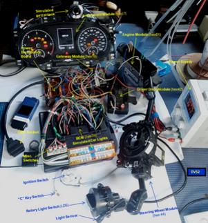
    Certainly, the new MIB does NOT have its own light sensor - as I indicated in a previous reply, the new MIB takes the output reading from the photo-transistor in the instrument module and it modifies this signal via the values in adaptation channels that I listed

    As for your mention of the HVAC Cimatronic screen, this is simply just another display from the new MIB unit - so, the illumination level of this particular screen is affected by the underlying MIB settings - as are ALL other MiB screens

    Originally posted by SandSeeker View Post
    However, I was thinking, is it possible that the instrument cluster is not able to communicate with the MIB? or probably this sensor in the instrument cluster is not active or not coded in Adaptation of the instrument cluster?
    Hmm....... again, there is only ONE light sensor that modulates the illumination level of cabin displays/screens (i.e. the photo-transistor). If the illumination level of the clocks/LEDs on the instrument cluster changes with changing cabin light-levels - then the photo-transistor is operating OK. As to what is causing the problem on modules other than the instrument module, I'm not sure - hence my request for the adaptation channel information!

    Are you aware of "admaps" from VCDS devices and are you comfortable with creating and posting-up an admap for the instrument module?
    Last edited by DV52; 30-06-2024, 11:53 AM.
    Please don't PM to ask questions about coding, or vehicle repairs. The better place to deal with these matters is in the forum proper. That way you get the benefit of the wider expertise of other forum members! Thank you.

    Comment


    • Originally posted by DV52 View Post
      The channels in my previous post can ONLY be found in the new MIB.
      Great, today I'm going to check if the channels are active or not and the values stored just in case, thank you so much!!!!


      Originally posted by DV52 View Post
      But as I now understand, the "Climatronic" is the Climatronic screen on the MIB - it's NOT the illumination level on the Air-Conditioner panel
      No, my issues are, in general, two:

      1- The brightness of the screen of my MIB. The brightness is always static, same brightness during the night or during the day.

      2- The brightness of the small Climatronic screens: In my Climatronic panel, there are two small screens showing the number of the temperature selected, one for the driver and another one for the passenger. This two small screens have always same static brightness as the MIB Screen, too dark always.


      Originally posted by DV52 View Post
      hmm.... with the important caveat that I'm not familiar with a Golf mk5, I would be very surprised if the original RNS-510 had a separate light sensor.
      Yes, the RNS-510 has its own and independent brightness sensor in the front panel. I have tested it before.


      Originally posted by DV52 View Post
      If the illumination level of the clocks/LEDs on the instrument cluster changes with changing cabin light-levels - then the photo-transistor is operating OK.
      Yes, it is changing correctly the brightness of the instrument cluster yes, I assume then the photo-transistor is working fine.


      Originally posted by DV52 View Post
      Are you aware of "admaps" from VCDS devices and are you comfortable with creating and posting-up an admap for the instrument module?
      I don't know about "admaps" from VCDS devices, but if you can guide me a little bit on how to do it, I can do it, no problem for me. But I believe that the instrument cluster photo-transistor is working fine.

      However, today I'm going to check all the values for the channels you mentioned in your previous post for the MIB. I should probably check the values in the dark and in the daylight?

      Thanks again for all your help!!! I really appreciate it!
      Last edited by SandSeeker; 30-06-2024, 10:42 PM.

      Comment


      • Originally posted by DV52 View Post
        I note that your 5C0035680D module also has 2 x sets of "X/Y" axis adaptation channels that look very similar to the mk7 set-up - but I'm not sure how they operate on a PQ35 platform car.

        Anyhow -maybe post-up the current values for the following channels in your new MIB:

        Dimming_Ambient_Illumination_Information_Control_U nit-X1
        Dimming_Ambient_Illumination_Information_Control_U nit-X2
        Dimming_Ambient_Illumination_Information_Control_U nit-X3
        Dimming_Ambient_Illumination_Information_Control_U nit-Y1
        Dimming_Ambient_Illumination_Information_Control_U nit-Y2
        Dimming_Ambient_Illumination_Information_Control_U nit-Y3

        Dimming_Illumination_for_Display_Unit-X1
        Dimming_Illumination_for_Display_Unit-X2
        Dimming_Illumination_for_Display_Unit-X3
        Dimming_Illumination_for_Display_Unit-X4
        Dimming_Illumination_for_Display_Unit-X5
        Dimming_Illumination_for_Display_Unit-X6
        Dimming_Illumination_for_Display_Unit-Y1
        Dimming_Illumination_for_Display_Unit-Y2
        Dimming_Illumination_for_Display_Unit-Y3
        Dimming_Illumination_for_Display_Unit-Y4
        Dimming_Illumination_for_Display_Unit-Y5
        Dimming_Illumination_for_Display_Unit-Y6

        Hopefully the channels above act in the same way as on a mk7 and the solution to your display problem is just a coding change (yes, my hunch is a bit of a long-shot, but it's an easy try -so worth considering IMO)

        Hi Don,

        Here we are, the current values stored in my new MIB for the channels are the following:

        Dimming_Ambient_Illumination_Information_Control_U nit-X1 ---> 0
        Dimming_Ambient_Illumination_Information_Control_U nit-X2 ---> 20
        Dimming_Ambient_Illumination_Information_Control_U nit-X3 ---> 50
        Dimming_Ambient_Illumination_Information_Control_U nit-Y1 ---> 0
        Dimming_Ambient_Illumination_Information_Control_U nit-Y2 ---> 20
        Dimming_Ambient_Illumination_Information_Control_U nit-Y3 ---> 50

        Dimming_Illumination_for_Display_Unit-X1 ---> 3
        Dimming_Illumination_for_Display_Unit-X2 ---> 10
        Dimming_Illumination_for_Display_Unit-X3 ---> 15
        Dimming_Illumination_for_Display_Unit-X4 ---> 60
        Dimming_Illumination_for_Display_Unit-X5 ---> 0
        Dimming_Illumination_for_Display_Unit-X6 ---> 0
        Dimming_Illumination_for_Display_Unit-Y1 ---> 2%
        Dimming_Illumination_for_Display_Unit-Y2 ---> 10%
        Dimming_Illumination_for_Display_Unit-Y3 ---> 15%
        Dimming_Illumination_for_Display_Unit-Y4 ---> 90%
        Dimming_Illumination_for_Display_Unit-Y5 ---> 0%
        Dimming_Illumination_for_Display_Unit-Y6 ---> 0%

        Comment


        • SandSeeker: OK - thanks for the information!

          Once more for emphasis - from your responses in the first part of your last reply - it DOES appear that stuff is different on this Golf mk5 (no surprise given the different build platform, I guess!)

          The differences in your explanation means that you will need to experiment with my suggestions -so, NO guarantees!!

          I suggest that the appropriate channel grouping for this problem is Dimming_Illumination_for_Display_Unit

          First, the fundamentals about "Dimming Illumination" channels:
          1. If there is a similarity with MQB platform cars and as I said in my first reply, the set of X/Y values for the group of channels represents points on a graph - with the axes defined like this:
          Each X-channel refers to a particular level of cabin illumination (i.e. a particular photo-transistor voltage value)
          Each Y-channel specifies the dimming level output for the corresponding X-channel value


          2. Again if stuff is the same - Increasing X values represent increasing light-levels in the cabin - so X6 is the highest cabin light-level and X5 is the next lower cabin light-level.....etc

          3. I suspect that the lowest X/Y values (i.e. X1 & Y1) refers to illumination levels when low-beam lights are switched-ON. When this happens, the photo-transistor ceases to control the lighting levels of cabin screens/displays. Instead, control is transferred to the "T58" signal and the illumination level is set by the dashboard lighting rheostat -but I'm guessing!!

          4. It appears that the "Dimming Illumination" channel values in the MIB are decimal numbers - so the range of allowable values = 0 -> 100 (this isn't necessarily the case in other modules which often use hexadecimal numbers)

          So, for the Dimming_Illumination_for_Display group of channels - maybe try increasing the values of Y6 and Y5 If this doesn't work, maybe try increasing Y1?

          Finally, I STRONGLY suggest that you make careful notes of each change when experimenting. This will be useful if stuff goes pear-shape - simply reset the values in your notes by reverting changes back to the original settings. Then, start again!

          Don
          Last edited by DV52; 01-07-2024, 12:00 PM.
          Please don't PM to ask questions about coding, or vehicle repairs. The better place to deal with these matters is in the forum proper. That way you get the benefit of the wider expertise of other forum members! Thank you.

          Comment


          • Originally posted by DV52 View Post
            SandSeeker: OK - thanks for the information!

            Once more for emphasis - from your responses in the first part of your last reply - it DOES appear that stuff is different on this Golf mk5 (no surprise given the different build platform, I guess!)

            The differences in your explanation means that you will need to experiment with my suggestions -so, NO guarantees!!

            I suggest that the appropriate channel grouping for this problem is Dimming_Illumination_for_Display_Unit

            First, the fundamentals about "Dimming Illumination" channels:
            1. If there is a similarity with MQB platform cars and as I said in my first reply, the set of X/Y values for the group of channels represents points on a graph - with the axes defined like this:
            Each X-channel refers to a particular level of cabin illumination (i.e. a particular photo-transistor voltage value)
            Each Y-channel specifies the dimming level output for the corresponding X-channel value


            2. Again if stuff is the same - Increasing X values represent increasing light-levels in the cabin - so X6 is the highest cabin light-level and X5 is the next lower cabin light-level.....etc

            3. I suspect that the lowest X/Y values (i.e. X1 & Y1) refers to illumination levels when low-beam lights are switched-ON. When this happens, the photo-transistor ceases to control the lighting levels of cabin screens/displays. Instead, control is transferred to the "T58" signal and the illumination level is set by the dashboard lighting rheostat -but I'm guessing!!

            4. It appears that the "Dimming Illumination" channel values in the MIB are decimal numbers - so the range of allowable values = 0 -> 100 (this isn't necessarily the case in other modules which often use hexadecimal numbers)

            So, for the Dimming_Illumination_for_Display group of channels - maybe try increasing the values of Y6 and Y5 If this doesn't work, maybe try increasing Y1?

            Finally, I STRONGLY suggest that you make careful notes of each change when experimenting. This will be useful if stuff goes pear-shape - simply reset the values in your notes by reverting changes back to the original settings. Then, start again!

            Don


            Hi Don,


            Thank you so much for your great explanation about the brightness subject. I assume that all the tests does not have any guarantee. Today I revised everything you suggested me to try, but I had all the time no success. The thing is, every time I wanted to set a new value to have a try, a different error or information message window was coming up from VCDS without saving the desired value. I'm attaching screenshots... What a nightmare this the brightness issue...

            Click image for larger version

Name:	IMG_1391.jpg
Views:	1
Size:	129.5 KB
ID:	1861645

            Click image for larger version

Name:	IMG_1394.jpg
Views:	1
Size:	390.0 KB
ID:	1861646

            Click image for larger version

Name:	IMG_1395.jpg
Views:	1
Size:	326.6 KB
ID:	1861644


            Today I realized something about the button in the dash for the dashboard brightness regulation, that allows me to set the brightness dashboard lights and illumination from the cluster, MIB screen and all the buttons illumination. This button, is only working when I put the switch of the lights to the Automatic mode and the maximum brightness is not enough.

            If I put the switch of the lights to the OFF position, then the brightness changes to the same as the maximum brightness from this button, but then, the button does not work, and the maximum brightness is still not enough.


            About the MIB options, I also have realized a couple of things:
            1- If I deactivate the option "Animation when finger near screen", then the brightness increases a little bit.
            2- In my MIB Settings, and Screen, does not appears the option showed in the following image, the "Day/Night", don't know why...

            Click image for larger version

Name:	IMG_1369.jpg
Views:	1
Size:	107.7 KB
ID:	1861647

            And the option above, "Brightness", is settled to "Very bright". And the brightness still not enough.

            Thanks a lot.
            Last edited by SandSeeker; 02-07-2024, 11:12 AM.

            Comment


            • hmm........ i suspect from the error message in the dialogue box which says "Service not supported in active session" that you probably need to change the diagnostic session for the 5F module to Developer mode before attempting the channel changes.

              I'm not sure if you are aware how to do this - if not, follow the instructions below before attempting the coding changes:

              VCDS: Change diagnostic session to Developer Mode (5F module)
              1. Navigate to the Open Controller screen for the 5F Module and select Security Code-16
              2. Enter S12345 as the security code (depending on the VCDS software version - the security code may appear in the dialogue balloon) and press Do it!
              3. Back on the Open Controller screen, select Adaptation-10
              4. Enter 'IDE02122" into the search box and select IDE02122-Developer mode
              5. Change value to activated
              6. The current VCDS diagnostic session for the 5F module is now Developer mode


              Don
              Last edited by DV52; 02-07-2024, 05:27 PM.
              Please don't PM to ask questions about coding, or vehicle repairs. The better place to deal with these matters is in the forum proper. That way you get the benefit of the wider expertise of other forum members! Thank you.

              Comment


              • Originally posted by DV52 View Post
                hmm........ i suspect from the error message in the dialogue box which says "Service not supported in active session" that you probably need to change the diagnostic session for the 5F module to Developer mode before attempting the channel changes.

                I'm not sure if you are aware how to do this - if not, follow the instructions below before attempting the coding changes:

                VCDS: Change diagnostic session to Developer Mode (5F module)
                1. Navigate to the Open Controller screen for the 5F Module and select Security Code-16
                2. Enter S12345 as the security code (depending on the VCDS software version - the security code may appear in the dialogue balloon) and press Do it!
                3. Back on the Open Controller screen, select Adaptation-10
                4. Enter 'IDE02122" into the search box and select IDE02122-Developer mode
                5. Change value to activated
                6. The current VCDS diagnostic session for the 5F module is now Developer mode


                Don

                Thank you so much Don! and sorry for late reply.

                I have followed all your instructions to change the diagnostic session to developer mode. At the beginning, all the steps you have mentioned are ok and no problems at all. But my surprise was, when I tried to change the values any of the dimming illumination channel, as before, the results were exactly the same. Except the ERROR about the Session one, it did not appear again. I also have realized I have to go and put the Security Code for each channel I want to modify every time. Unfortunately, every time I try to change any value of any of this channels, the errors are coming up. I'm going to attach some examples:

                Click image for larger version

Name:	IMG_1534.jpg
Views:	1
Size:	173.6 KB
ID:	1861657

                Click image for larger version

Name:	IMG_1535.jpg
Views:	1
Size:	177.9 KB
ID:	1861658

                Click image for larger version

Name:	IMG_1536.jpg
Views:	1
Size:	180.1 KB
ID:	1861659

                Click image for larger version

Name:	IMG_1540.jpg
Views:	1
Size:	176.3 KB
ID:	1861660

                I'm starting to be a liitle bit worried/desperate about wether is going to be possible to solve my issue in any way, even if the process is difficult, I have no problem to go ahead and do all the necessary things to be able achieve it!


                In the other hand, I remember long time ago I swapped one of my modules for a newer one, I think this was the central Electric one, I'm not sure, but probably this could be a good start if at the end I find myself forced to go ahead with more difficult solutions. Picture of the old Module with all the connectors.

                Click image for larger version

Name:	IMG_1419.jpg
Views:	1
Size:	195.8 KB
ID:	1861661

                Click image for larger version

Name:	IMG_1420.jpg
Views:	1
Size:	200.1 KB
ID:	1861662

                Any advice about how to continue my tests would be very appreciate it.

                Thanks a lot.

                Comment


                • Hi, good evening from Spain.

                  Finally and after some days, I got an answer from the developer of the PCB that solves the issue about the brightness in the MIB in a car with CECM instead a BCM, and also in the small screen showing the numbers of the temperature in the retrofitted Climatronic. So, hopefully, I will get it soon.

                  In the other hand, about the rear view camera (RVC) I also needed to change it from one with 1080p resolution to another one with 720p resolution, however, the quality and the brightness and colors of the image is much better. I give you the Aliexpress Link. The Lines are supposed to be dynamic ones, the system is not from CAN_BUS, is about an internal gyroscope, strange, but at least RVC is working fine!


                  Thanks a lot, I will keep you updated soon!

                  Comment


                  • Hi, Good evening.

                    Finally I have received the PCB, I have installed it and the problem was completely solved.
                    For now, at least, the best solution.


                    Thanks!!

                    Comment


                    • If anyone is still after this retrofit, I sold my car and removed mine. Have pretty much everything you need, including the correct highline reverse camera module.

                      Screen has developed some phantom touch issues though (as they all seem to) but this can be fixed

                      Comment


                      • @merckxite: I'm contemplating adding a MIB to my test-bench (see below), so the "phantom touch issues" are not a problem. However, I'm not prepared to throw much money at the project!!

                        How much do you want for the MIB (I don't need the camera) and can you provide part numbers for the MIB? Do you have the screen a too?

                        Don
                        Please don't PM to ask questions about coding, or vehicle repairs. The better place to deal with these matters is in the forum proper. That way you get the benefit of the wider expertise of other forum members! Thank you.

                        Comment


                        • Originally posted by DV52 View Post
                          @merckxite: I'm contemplating adding a MIB to my test-bench (see below), so the "phantom touch issues" are not a problem. However, I'm not prepared to throw much money at the project!!

                          How much do you want for the MIB (I don't need the camera) and can you provide part numbers for the MIB? Do you have the screen a too?

                          Don
                          Hi Don, the unit is a Composition Media, 5K7035200L (SW0472, HW H41). App Connect functionality activated and CP removed. Will DM you the details

                          Comment


                          • Hi mates,


                            I've been working on a retrofit project of a Discover Media PQ (5C0035680G with 0478 SW version - MST2_EU_VW_PQ_P0478T)
                            into a 2010 VW Golf 6 SW.

                            This is what I've accomplished so far:

                            I removed the old Bluetooth module under the passenger's seat, re-used the existing microphone and plug it into the new unit.
                            Had to do a small re-wiring of the 2 microphone wires into the radio harness adaptor but nothing complicated.

                            I also upgraded my Gateway to a 7N0 907 530 BF in order to be able to access the 5F module of the Discover Media.

                            As Kamold said on page 4 of this thread, its pretty much straight forward.

                            Was also able to enable some FEC / Swap codes such as:

                            - Off Road information Menu,
                            - Driving School Menu,
                            - and Performances Monitor as well.


                            Regarding the Off Road information Menu, all gauges are working fine. (wheel angle rotation, compass and altitude)

                            However, regarding the Performances Monitor, I don't have the same standard gauges showing, as in the Golf 7 GTD, for example.

                            When I want to change / switch the gauges, I miss the Boost Pressure gauge in bar, and the torque gauge in kW.

                            I can only switch between coolant temperature gauge (not working), Oil temperature gauge (this one works) and a third one that has
                            a g unit, but shows also nothing.

                            Did anyone of you ever had this issue?
                            Would you know by chance the reason for this?
                            Should I re-install anything or still activate something on 5F module?

                            Thanks in advance for your help.

                            Click image for larger version

Name:	Performances Monitor.jpg
Views:	1
Size:	157.3 KB
ID:	1861907

                            Comment


                            • Performance monitor does not work in pq cars.


                              Sent from my SM-S921B using Tapatalk
                              2011 Skoda Octavia vRS TDI DSG wagon|Revo Stage 1|Race Blue|Leather|Dynamic Xenons w 6000K|9w7 BT|THA475 Amp+active sub|Whiteline ALK|RVC|
                              2009 R36 wagon|Biscay Blue|RVC|Tailgate|ECU and DSG tune|LED DRL/Indicators|3D colour cluster|Quad LED tail rings|Climatronics upgrade|Dynaudio retrofit|B7 RLine Flat Steering Wheel|3AA CCM|TPMS Direct|B7 Adaptive Cruise with Front Assist|Discover Media retrofit|PLA 2.0|Lane Assist|BCM retrofit|High Beam Assist|DQ500

                              Comment


                              • Originally posted by kamold View Post
                                Performance monitor does not work in pq cars.


                                Sent from my SM-S921B using Tapatalk
                                Hi Kamold,

                                thanks for your feedback.
                                Okay, then I know why now.

                                I have another issue:

                                the stand by clock, shows me a strange date when I put the Radio in standby mode.
                                It shows me 31.01.2047 and I can't find a setting to adjust it...

                                Any idea why ?

                                Click image for larger version

Name:	Datum Problem.jpg
Views:	1
Size:	158.2 KB
ID:	1861908

                                Comment

                                Working...
                                X