 Tweet
Tweet
Originally posted by MK7Golfer
View Post
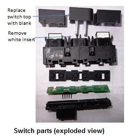
First a picture of the switch base which contains the LEDs and the driving electronics (I've shown the "switch pads" for the Park Assist and Garage opener switches for later reference.
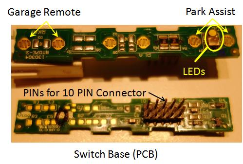
Notice that only one LED-set is populated (for the existing Park Assist switch). I guess that it really doesn't matter if the LED for the Garage Remote isn't on the PCB since the general illumination LED that's missing from between the 2 switch-pads at the end of the PCB isn't needed
2nd picture shows the part that I have called the "White insert" in my first post:
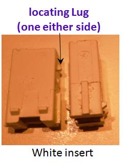
The white insert connects to the switch cap. The way that the two pieces connect is via the locating lugs shown in the picture above - there is a matching set of mating tags on the underside of the switch cap which holds the cap to the insert (see picture below). The bottom of the white insert pushes onto the "graphite pad" that sits on the switch-pads in the picture above. There is only one "white insert" on the existing switch (which lines-up with the Park Assist position)
3rd picture shows the underside of a switch cap compared to the underside of a blank cap (sorry that the pic isn't crisp!):
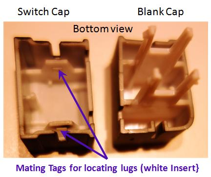
As you can see, the important part of the switch cap is the mating tags (for the lugs on the "white insert") - the blank cap doesn't have these tags. When I first started this project, I tried grinding back the insides of a blank cap, but the process was too fiddly to work!
I'm also not sure if marking the function of the switch cap for the garage opener is such a good idea (as per your link). My preference is NOT to advertise where the garage opener is in the car - you will know where the switch is and that's all that's needed. But if you want to spend the money getting a fancy switch cap symbol (something cryptic), then that's OK too.
Cheers
Don
PS: Yes, the unit that I show in my first post is a black satin switch module

Comment