 Tweet
Tweet
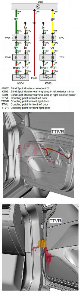
I was all prepared to have an auto-electrician tap into the wiring to add a couple of LEDs to my dash which would light up if someone was in the blind spot. He no as he thought the "Can bus " might be upset and problems created.
Can anyone confirm if he is correct please, or is there a way to do it without upsetting the Can bus?
Can anyone confirm if he is correct please, or is there a way to do it without upsetting the Can bus?

")
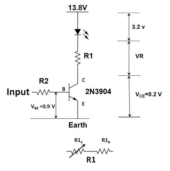
 . I get 0.58 V to the Emitter. That is by the needle in the yellow.
Comment