 Tweet
Tweet
There are a few threads on this, but thought I'd put something together to explain.
Going to need to do this with borrowed photos, etc.
------------------------------------------------
What is it? Removal of the Secondry Air system on the Polo GTI (may suit other vehicles).
Why: The pump / combi valve is prone to failiure and the Vac system is not required (IMO) after the SAI is removed:
The Vac system includes N249 control which allows the ECU to modify the boost slightly
The 249 also regulates the VAC to the diverter valve, for tuned Polos, some have found more consistant boost or better diverter action (noise) from bypassing.
Downside: As I understand (so not necessarily correct) The SAI system is designed to reduce emissions by heating up the CAT faster
What is required:
For my car (should suit Polo 9N3's as a whole, but don't quote me on that) best results have been experinced with the following parts:
2 x IE Oval shaped Resistor Plug
1 x IE Resistor (they cost very little I'd get 2, just in case)
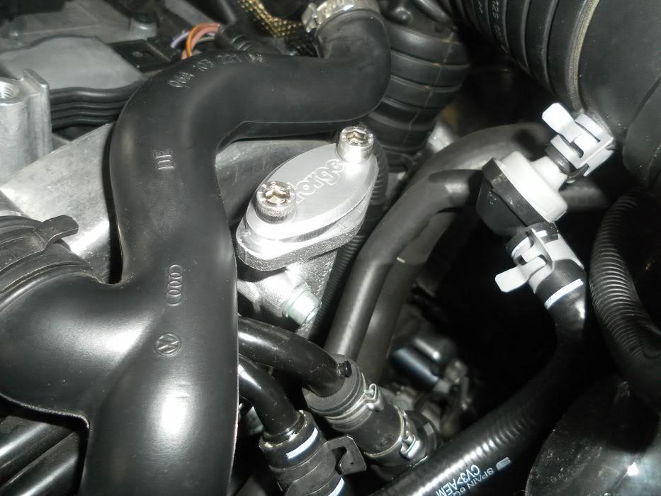
IE SAI blanking plate There are a few places to get these
As postage is significant, group buys are prob the best way to go.
-------------------------------
Asside from the above, you are likely to need a few bits and peices that can be locally sourced or may be in your stock of car crap;
- Top up of G12++ coolant as some is lost in the process (volume TBC based on Jmac's help of how not to loose a lot)
- 1 meter of vac line (as its cheap, get more). I think 3mm or 4mm is what suits, you can cut off 1cm from your existing vac lines and take it in to a auto store to see what is suitable. You are better off with forcing on something to small rather than larger, looser fitting piping.
- A few decent small cable ties
- Basic Hex / security bit set and tools (I have a mini ratchet set I use frequently).
Overview;
So again, I have to apologise for borrowing someone elses photo for this. If I've used a photo of yours and you don't want me to, please let me know and I'll take it down.
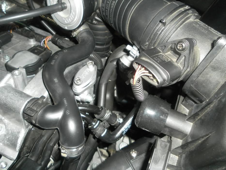
Once the engine cover is off, your engine looks something like this;
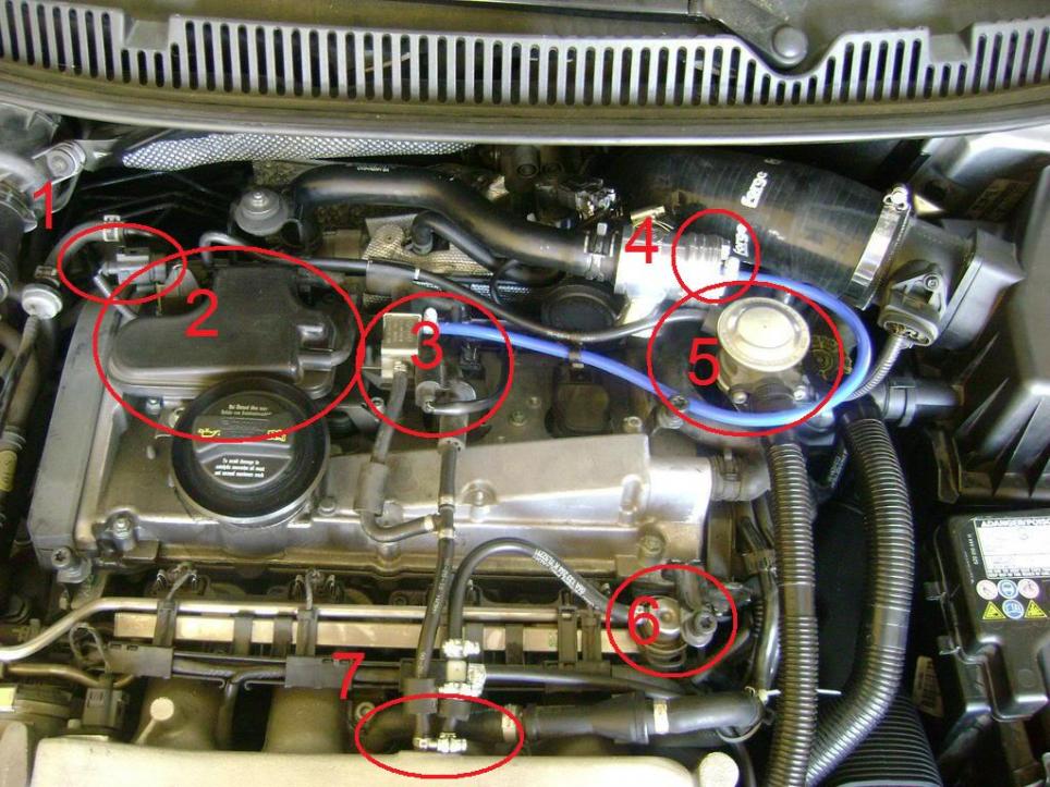
1 The SAI Sensor electrical socket - use one resistor plug
2 The VAC resoervoir system, junk and bracket (held on with 3 bolts, small socket set to remove)
3 N249 system and electrical connection - bypass this
4 Diverter Valve - connect vac line to manifold
5 Combi Valve - this is to be removed when the bolts attaching it to the engine are removed
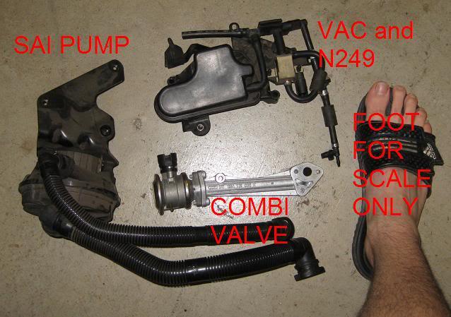
A few reference photos from when i did this originally (threw codes, so put it back)
the removed parts:
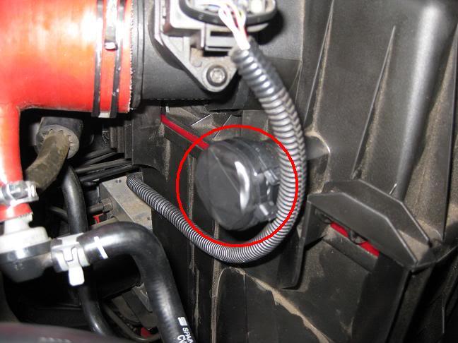
Small blanking plate I cut from plastic and taped over the stock airbox hole
Procedure:
Remove the vac lines:
- From the intake manifold to the VAC / 249 System
- From the N249 to the dverter
- From the vac system to the combi valve
- Run a new vac line direct from the manifold to the diverter. you should also have another line from the mani to the FPR still.
Disconnect the 2 electrical connections (Vac at #1, N249 at #3).
Remove the 3 bolts that mount the SAI system onto the top of the engine block.
The SAI system should lift loose, ready for storage / bin.
Use the 2 oval resistors in the SAI and N249 electrical plugs.
Thats part 1 done.
Part 2 I'll try and get some more photos for.
Disconnect the 2 flex hoses that run to the combi valve and Airbox.
Plug the airbox hole (I cut a circle from thick plastic and used tape and a cable tie to keep in place)
The SAI pump is located in front of the intake mainfold. The bracket that the dipstick clips into holds the SAI pump in place.
Disconnect the SAI pump electrical plug and tock airbox pipe / PD160.
The pump is held in by 3 bolts, one where the dipstick mounts and 2 through the top of the mainfold. they form a triangle.
Remove these 3 bolts, whilst supporting the pump. The bolt nearest the dipstick mounts a seperate bracket on, mind you don't drop this.
The pump should lift out towards the battery.
Use the bare resistor in the end of the pump's electrical connection (I again used electrical tape and a cable tie to secure).
The last part is removing the Combi valve, this bit requires good access to the side of the engine, removing the flex pipes for the pump has helped with access / visibility.
In order to access the 3 bolts at the bottom of the combi, a coolant pipe (well, 3 that join at the side of the block) needs to be removed. If you remove the coolant pipes, you loose a large amount of coolant. I'm hoping to be able to clamp the 3 pipes around this and not loose all my fluids.
Going to need to do this with borrowed photos, etc.
------------------------------------------------
What is it? Removal of the Secondry Air system on the Polo GTI (may suit other vehicles).
Why: The pump / combi valve is prone to failiure and the Vac system is not required (IMO) after the SAI is removed:
The Vac system includes N249 control which allows the ECU to modify the boost slightly
The 249 also regulates the VAC to the diverter valve, for tuned Polos, some have found more consistant boost or better diverter action (noise) from bypassing.
Downside: As I understand (so not necessarily correct) The SAI system is designed to reduce emissions by heating up the CAT faster
What is required:
For my car (should suit Polo 9N3's as a whole, but don't quote me on that) best results have been experinced with the following parts:
2 x IE Oval shaped Resistor Plug
1 x IE Resistor (they cost very little I'd get 2, just in case)
IE SAI blanking plate There are a few places to get these
As postage is significant, group buys are prob the best way to go.
-------------------------------
Asside from the above, you are likely to need a few bits and peices that can be locally sourced or may be in your stock of car crap;
- Top up of G12++ coolant as some is lost in the process (volume TBC based on Jmac's help of how not to loose a lot)
- 1 meter of vac line (as its cheap, get more). I think 3mm or 4mm is what suits, you can cut off 1cm from your existing vac lines and take it in to a auto store to see what is suitable. You are better off with forcing on something to small rather than larger, looser fitting piping.
- A few decent small cable ties
- Basic Hex / security bit set and tools (I have a mini ratchet set I use frequently).
Overview;
So again, I have to apologise for borrowing someone elses photo for this. If I've used a photo of yours and you don't want me to, please let me know and I'll take it down.
Once the engine cover is off, your engine looks something like this;
1 The SAI Sensor electrical socket - use one resistor plug
2 The VAC resoervoir system, junk and bracket (held on with 3 bolts, small socket set to remove)
3 N249 system and electrical connection - bypass this
4 Diverter Valve - connect vac line to manifold
5 Combi Valve - this is to be removed when the bolts attaching it to the engine are removed
A few reference photos from when i did this originally (threw codes, so put it back)
the removed parts:
Small blanking plate I cut from plastic and taped over the stock airbox hole
Procedure:
Remove the vac lines:
- From the intake manifold to the VAC / 249 System
- From the N249 to the dverter
- From the vac system to the combi valve
- Run a new vac line direct from the manifold to the diverter. you should also have another line from the mani to the FPR still.
Disconnect the 2 electrical connections (Vac at #1, N249 at #3).
Remove the 3 bolts that mount the SAI system onto the top of the engine block.
The SAI system should lift loose, ready for storage / bin.
Use the 2 oval resistors in the SAI and N249 electrical plugs.
Thats part 1 done.
Part 2 I'll try and get some more photos for.
Disconnect the 2 flex hoses that run to the combi valve and Airbox.
Plug the airbox hole (I cut a circle from thick plastic and used tape and a cable tie to keep in place)
The SAI pump is located in front of the intake mainfold. The bracket that the dipstick clips into holds the SAI pump in place.
Disconnect the SAI pump electrical plug and tock airbox pipe / PD160.
The pump is held in by 3 bolts, one where the dipstick mounts and 2 through the top of the mainfold. they form a triangle.
Remove these 3 bolts, whilst supporting the pump. The bolt nearest the dipstick mounts a seperate bracket on, mind you don't drop this.
The pump should lift out towards the battery.
Use the bare resistor in the end of the pump's electrical connection (I again used electrical tape and a cable tie to secure).
The last part is removing the Combi valve, this bit requires good access to the side of the engine, removing the flex pipes for the pump has helped with access / visibility.
In order to access the 3 bolts at the bottom of the combi, a coolant pipe (well, 3 that join at the side of the block) needs to be removed. If you remove the coolant pipes, you loose a large amount of coolant. I'm hoping to be able to clamp the 3 pipes around this and not loose all my fluids.


Comment