 Tweet
Tweet
I have a spare crankshaft sensors I have tried, I checked the wiring from the plug back to the ecu and have continuity, I bought a new crack shaft sensor (g2 and still no start or engine speed while cranking, I now have a bad feeling that something has fried the ecu, any fresh ideas for me please.
-
-
@Peedee61: Of course anything is possible - so there is a finite probability that the internal circuits in the ECU have gone pear-shape. However, I suspect that the probability of the problem here being a component failure external to the ECU is far greater!!
I'm not sure which particular engine is installed in this car - but it's quite likely that G28 is a Hall-effect sensor (i.e. this engine does NOT use an inductive type speed sensor). My assumption can be confirmed if the sensor has a 3 x pin connector.
The general set-up for a Hall effect sensor is like this (I thieved the picture from the web) :
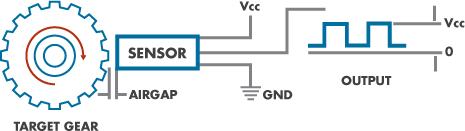
As you can see- these senors use an external power supply (labelled "Vcc" in my diagram). In your engine, this power-supply is 5Volts - which is generated by the ECU. There is also a ground pin for the 5Volts which is different to car earth and the remaining pin is the pulsed voltage that is the speed signal to the ECU.
I'm not sure about this particular G28 sensor - but normally on these 3 x pin connectors:- 5 Volts = pin #1
- Signal = pin #2
- Earth = pin #3
The best way to check the operation of this sensor is with an oscilloscope because it will show how the voltages change with time - but it's unlikely that you will have access to a scope. There are a number of You-tube videos that describe how to use a multi-meter to check the operation of Hall-effect sensors
So - the way to check the wiring for this sensor is to grab a multi-meter and first measure if the +5Volt power supply is present at the 3 x pin sensor connector. It's unlikely that the +5Volt supply from the ECU is faulty because this same power supply is used for other Hall-effect sensors on the engine -but it may be absent at the connector on this particular sensor.
The other possible reason for this fault could be the condition of the air-gap between the sensor and the toothed wheel. Shine a torch onto the gap and check that it's clean and free from detritus.
DonLast edited by DV52; 26-02-2024, 09:59 AM.Please don't PM to ask questions about coding, or vehicle repairs. The better place to deal with these matters is in the forum proper. That way you get the benefit of the wider expertise of other forum members! Thank you. -
Hi DV 52 yes it is the 3 pin sensor, it has the 5 volt supply from the ecu it has the negative feed from the pin at the sensor, no unfortunately I do not have access to an oscilloscope,
would passing a metal object in front of the sensor create a 5 volt return to ecu ( which is what I believe it should be) as I stated I have traced the wiring from the ecu to the sensor and have continuity on all 3 wires
the engine is the cabby common rail diesel of 103 kw I replaced this motor in June and still have not managed to get it to run, when attempting to start I get 0 rpm but get other items that show reasonably correctly to specs, such as high fuel pressure starts at 8 bar but quickly jumps to around 40 to 45 bar I get injector pulse length and quantity, I can smell the exhaust is so close to the start after a prolonged crank .
i have had the top of this motor off to double check there was no physical mechanical issue, and I have replaced the rear main seal as it was 1 leaking and 2 the timing ring had been set aligned with the sensor not at the correct spot while at tdc, which I did by buying the correct tool to install and align it.
thank you for your input.
one question if I go looking at ecu’s would buying the complete set of immobiliser, key, and ecu be better and just work asplug and play or just get the ecu and have it coded, I do not trust our local dealer he had the car for 3 weeks claimed it was the g28 crankshaft sensor but then also stated the engine that I had gotten from the wrecker was sold in Australia but they had no access to a wiring diagram for it, I’m currently using one that has been converted from Russian and all the wiring and colours have matched so far, got the feeling from them it’s only an older car who cares they should get a new oneComment
-
-
Is the engine code the same as what the ECU is from? It's common for the tone rings to change patterns between engines.
Also, regarding the immobiliser stuff, most VWs need ECU, keys and Cluster; you are better off matching the ECU to the existing VINLast edited by MIG; 25-02-2024, 08:39 PM.MY12 Passat FSI Highline | 3.6L VR6 | Cashmere Brown | Driver Assistance Package | Dynaudio | Discover Media | TPMS Direct | Side Assist | Adaptive Cruise | 3D colour cluster | More coming soon
Genuine VCDS HEX-NET and VCP ProComment
-
Hi yes the tone rings caused me all sorts of issues as mine has 2 raised teeth at 180 degrees apart the first one I got of eBay had holes in it and the seller insited that it was correct after having to send pictures to him showing the difference and stating I was not going to use it, my local parts supplier also was unsure so, I scoured the local sources and found repo had the correct one via picture but was miles away from me, so ordered it to my local store and if not correct would be able to leave it, when it arrived it was the correct tone ring.
The engine code is exactly the same the car it came out of was only a month younger than mine. Both CBAB prefix engines
Thank you that is one of my question's answered regarding the ecuLast edited by Peedee61; 26-02-2024, 08:03 AM.Comment
-
Are any errors stored on the ECU? A no signal or correlation error would help point us in the right direction.
Otherwise, without a scope, it's going to be hard to be certain what the issue is. (Pico scope is $180, multimeter scopes can be even cheaper)
Something like this.
000022 - Bank 1: CMP Sensor (G40) / Engine Speed Sensor (G2
P0016 - 000 - Incorrect CorrelationMY12 Passat FSI Highline | 3.6L VR6 | Cashmere Brown | Driver Assistance Package | Dynaudio | Discover Media | TPMS Direct | Side Assist | Adaptive Cruise | 3D colour cluster | More coming soon
Genuine VCDS HEX-NET and VCP ProComment
-
Yes (albeit I don't quite understand the bit about "a 5 volt return path")!Originally posted by Peedee61 View Post
Do the steps below as the first of a 2 x part test:- Remove the Hall-effect sensor from the car and plug-in the connector so that the sensor is energized properly
- Make sure that the sensor end is NOT near any metal parts - Switch-ON ignition.
- Switch the multi-meter to the 20V DC scale and connect the multi-meter negative lead to battery earth
- Connect the multi-meter +ve lead to the +5V pin on the sensor - is the reading +5V?
- Connect the multi-meter +ve lead to the earth pin on the sensor - is the reading near 0V?
- Connect the multi-meter +ve lead lead to the signal pin on the sensor
- Move a large spanner near the sensor - the actual reading on the multi-meter will vary depending on lots of things - but if the sensor is good, you should see a change in the multi-meter voltage reading from +5V to near 0V.
So, the steps above will test if the sensor is OK. However, the procedure above does NOT say anything about the ability of the sensor to provide a stream of kosher square-wave pulses to the ECU when bolted into the engine housing. To test the condition of the sensor-circuit (as distinct from the sensor itself) - you need to check if the "reluctance wheel" (i.e. the "tone rings" in @MIG response) and the air-gap is OK.
For the "sensor circuit" test - do this:- Replace the sensor back in its position on the engine
- Disable the engine so that it won't start (maybe disable the fuel system)
- With the multi-meter switched to 20V DC scale -connect the multi-meter +ve lead to the signal pin on the sensor and the -ve lead to battery earth
- with ignition -ON, slowly rotate the the crankshaft using a socket wrench with a long handle. If the reluctance wheel/air-gap is OK - you should see the voltage switch from +5V to near 0V as the crankshaft rotates. Note: it's important in this test that the lower voltage is close-to 0V - I've seen some sensor-circuit signals that look OK at the +5V end - but they have a high reading at the low-end of the square-wave. The ECU uses a "hysteresis-circuit" to detect the rising/trailing edge of the square-wave pulses - proper detection of the high/low points defines the way that the ECU understands the stream of pulses in the waveform. This means that the sensor signal needs to have an almost FULL 5V change to trigger the upper/lower threshold levels in the hysteresis design (apology for launching into techno-geek babble!! )
I like @MIG suggestion about buying a cheap scope. However, it's one thing to have access to such a device - but it's an entirely different matter to understand how to use it in a way that makes sense. Please don't take offense - I've absolutely no doubt that you could learn the operation of an oscilloscope (it ain't a difficult device to drive). The thing about an oscilloscope is getting the square wave pulses to stabilize on the screen - this requires a user to select the proper time base for the incoming signal plus the proper trigger mode. Again, not difficult - but it DOES require a basic understanding of time based signals and how to capture the pulses.
What @MIG said!!Originally posted by Peedee61 View PostLast edited by DV52; 26-02-2024, 01:41 PM.Please don't PM to ask questions about coding, or vehicle repairs. The better place to deal with these matters is in the forum proper. That way you get the benefit of the wider expertise of other forum members! Thank you.Comment
-
@Peedee61:
Here's the pin-out and wiring diagram for G28 on the Tiggy ECU for a CBAB engine:
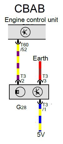
If you aren't familiar with VW nomenclature - T60 /52 means pin #52 on the ECU connector that has a total of 60 x pins.
DonLast edited by DV52; 26-02-2024, 01:39 PM.Please don't PM to ask questions about coding, or vehicle repairs. The better place to deal with these matters is in the forum proper. That way you get the benefit of the wider expertise of other forum members! Thank you.Comment
-
Hi DV52 I have traced the wiring from the sensor pin 1 in the connector has 5 volt power which is in the engine bay wiring harness, pin 3 has a continuous earth when measured with a multi meter and pin 2 the sensor wire has continuity to plug 60 at pin 54 ,the sensor wire goes to the 60 pin plug at the ecu and joins pin 52.
I did download the 19 page tutorial from ross tech on how to read the wiring diagrams and studied that for a couple of days to get my head around what seemed to be some strange language but eventually it made sense if thinking of it as an engineering diagram
I do have a code being coolant pump 2 short to ground, I have disconnected this plug and traced its wiring from plug T3bc pin one continuity to earth, pin 2 goes to fuse holder B fuse number 23 12 volt, pin 3 goes to the ecu plug with 94 pins and connects at pin 68 and has continuity.
I did have a code for p0016 CMP sensor (G4) / engine speed sensor (G28 ) incorrect correlation, which I re adjusted the cam timing with the tools and had the code cleared and has not returned.
Now I have a code for Engine speed sensor (g28 p0332 no signal since putting in the new sensor, (which by the way is a pain as you have to remove the oil filter/ cooler housing from the front of the engine to access the Allen key bolt, and there is no way that I can see to alter the sensor to tone ring gap as the sensor bolts to the engine block inside a gap in the bell housingLast edited by Peedee61; 26-02-2024, 06:01 PM.Comment
-
I've changed the structure of your sentence above so that I can better understand your words.Originally posted by Peedee61 View Post
I understand your pin #1 and pin #3 test - good results!!
But I don't understand your pin #2 result - how can pin #2 have "continuity to plug 60 at pin 54" AND the wire also "join pin 52" ?
On my Tiggy wiring diagram for the 2.0 ltr Diesel CBAB engine (from May 2010) - T60 /54 (i.e. pin #54 on the 60 x pin plug) is connected to one of the pins on the Coolant temperature sender G62 (which is a 2 x pin temperature variable resistor).
Again, my wiring diagrams for this engine say that the wiring for G28 is entirely independent to G62!! So - there should be no connection between pin #54 and pin #52 on the 60 x pin ECU plug
So, access to the sensor gap is problematic on this engine. OK - let's not bother with this visual test at this stage in our investigations. Complete my "sensor circuit" test with G28 installed.Originally posted by Peedee61 View Post
If you can't get access to the 3 x pin sensor connector with the sensor installed, you should be able to complete the test by connecting the multi-meter at the ECU plug. Or, you can connect to the wire that terminates onto pin #52. I sometimes use a small sewing-needle to pierce the wire to make contact to the copper strands - but take care not to break any wire-strands (so use the smallest sewing needle)!
DonLast edited by DV52; 27-02-2024, 08:40 AM.Please don't PM to ask questions about coding, or vehicle repairs. The better place to deal with these matters is in the forum proper. That way you get the benefit of the wider expertise of other forum members! Thank you.Comment
-
Yes I mucked that up in that pin 52 on the 60 pin ecu plug is the signal wire from the G28 crankshaft sensor, and meant to write pin 53 on the 60 pin plug is the earth for a large number of sensors and yes pin 54 is for a 2 pin temperature sensor, I have notes written on a book here but I have numbers and terminal numbers for different sensors all over the page, with lines trying to join them up and make sense of what I need to look at.
iam currently awaiting to hear from a friends grandson to see if I can borrow ( or even if he still has ) one of his grandfathers oscilloscopes, I would ask my friend himself but unfortunately after contracting COVID last year which had him in intensive care for 6 weeks after discharge to home from hospital, within 4 months of this he developed severe dementia and is now in a nursing home at the age of 70 and he had lots of electronics gear as at one stage that was part of his job as he was ex navy some of it he could not talk about but after retiring from the navy he mainly played with computers and televisions
I do appreciate your time and effortComment
-
@Peedee61: Arrhhh.......... that's much better -now I understand your pin-out description (and your latest words agree with my reading of the CBAB wiring diagram).
An oscilloscope can be particularly useful in situations where the fault in the sensor affects the running performance of a working engine. However, since this case appears to be one where the engine won't start at all - I'm guessing that the multi-meter test might be sufficient to ascertain if the basic sensor circuit is at least operational between the exchange engine and the factory installed ECUl!
It's not always the case that more sophisticated test devices give better answers!! But again, this is entirely your decision
Don
PS: sorry to read about your friend. We hear lots about COVID itself as a disease these days - but the dangers of long-COVID don't seem to get the same profile!!Please don't PM to ask questions about coding, or vehicle repairs. The better place to deal with these matters is in the forum proper. That way you get the benefit of the wider expertise of other forum members! Thank you.Comment
-
DV52 I will be trying to borrow or maybe even purchase one off the grandson, of my friend, as I feel it will be useful in the future anyway, my gp last week when I saw him stated that there is another strain of COVID currently running rampant, here in NSW.Comment
Comment