 Tweet
Tweet
Hi all!
First thing first
I have a 2016 Golf 7 SC with factory fitted trailer hitch and R-Line.
I´m just now fitting 2 external reversinglights wich will be flushmounted inside the "diffusor".
No problems with how to fit them to the car itselves, the problem starts with the electrics.
I want to connect the 2 external lights via a relay ( just to be safe ) so I need a signal from the original reversinglights and I was thinking, what better way to find that signal then on the cable for the trailer hitch.
It´s just that I dont get any signal at all when no trailer is attached. 0V in all 13 pins for the trailer.
I need your help with this.
The trailer hitch modul is 5Q0 907 383H
Is it possible to code it via VCDS so that I can get the reverselight signal even with no trailer attached?
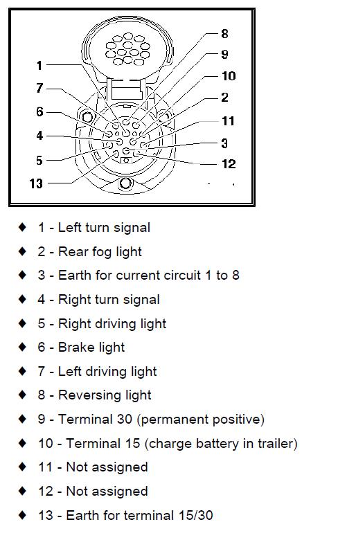
Does anyone have a pinout diagram for this trailer module?
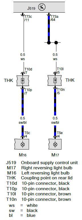
I do not know what colour the cable for reverselight have.
Soory for any bad spelling ( I´m swedish )
/ John
First thing first
I have a 2016 Golf 7 SC with factory fitted trailer hitch and R-Line.
I´m just now fitting 2 external reversinglights wich will be flushmounted inside the "diffusor".
No problems with how to fit them to the car itselves, the problem starts with the electrics.
I want to connect the 2 external lights via a relay ( just to be safe ) so I need a signal from the original reversinglights and I was thinking, what better way to find that signal then on the cable for the trailer hitch.
It´s just that I dont get any signal at all when no trailer is attached. 0V in all 13 pins for the trailer.
I need your help with this.
The trailer hitch modul is 5Q0 907 383H
Is it possible to code it via VCDS so that I can get the reverselight signal even with no trailer attached?
Does anyone have a pinout diagram for this trailer module?
I do not know what colour the cable for reverselight have.
Soory for any bad spelling ( I´m swedish )
/ John
Comment