 Tweet
Tweet
nice wheels man. poke looks sick. the sticker on your rear window suits it. are they standard brakes on the front??? they looks pretty big in a couple of the pics.
-
-
Standard late-model VR6 brakes - 288mm. They fill 15" wheels but I still have plenty of clearance with the 16" Equips!Comment
-
Have very good taste ray !! 1 cm poking out doesn't sound much but in real life it looks more dramatic.Comment
-
What can I say, that realy works very very very well... I want a set now!
that dish is gold...80,000km 1997 MK3 VR6 manual for sale - www.vwwatercooled.org.au/forums/f23/80-000km-1997-manual-vr6-nsw-sydney-67658.htmlComment
-
nice ray! just need some thinner stretched rubber and a lil more dumpage and you'll be rokin the nats! nice choice brah!
Comment
-
Love the wheels and stance Ray
Just needs to be dropped a tad more and stretch on them tyres as Alex said
Keep up the great work champ sigpic
| MY15.5 Mk3 Octavia vRS TSI | DSG | Black Pack | H&R Springs | 18" BBS RSII |Comment
-
This rims look too good to be legal, Ray.
Dave
Comment
-
I think it's my turn for an update!
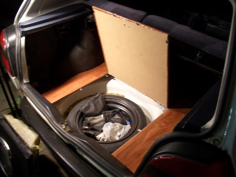
No I haven't fixed the dents yet, wide-track first so it doesn't look sus when it's being assessed! But I have done a false floor and battery relocation with the help of Louis. I couldn't have done it without him!
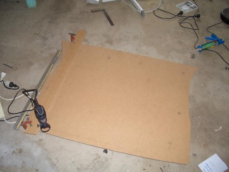
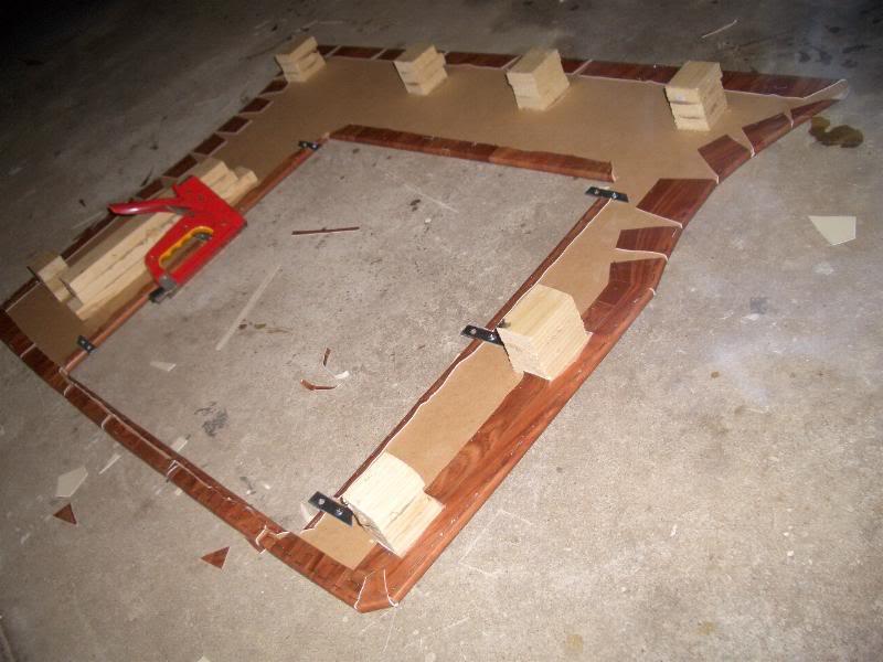
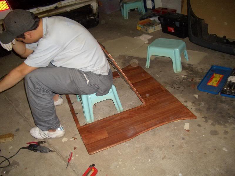
False floor was made out of MDF as it proved to be strong and cheap. I still had the factory carpet for the hatch so that was used as a template for the false floor. MANY cuts and trial fits were done to get it fitting nicely! Lots of time was spent at Bunnings with Louis and I tossing ideas back and forth. I wanted to try something different so we decided to cut a hole for taking out the spare wheel.
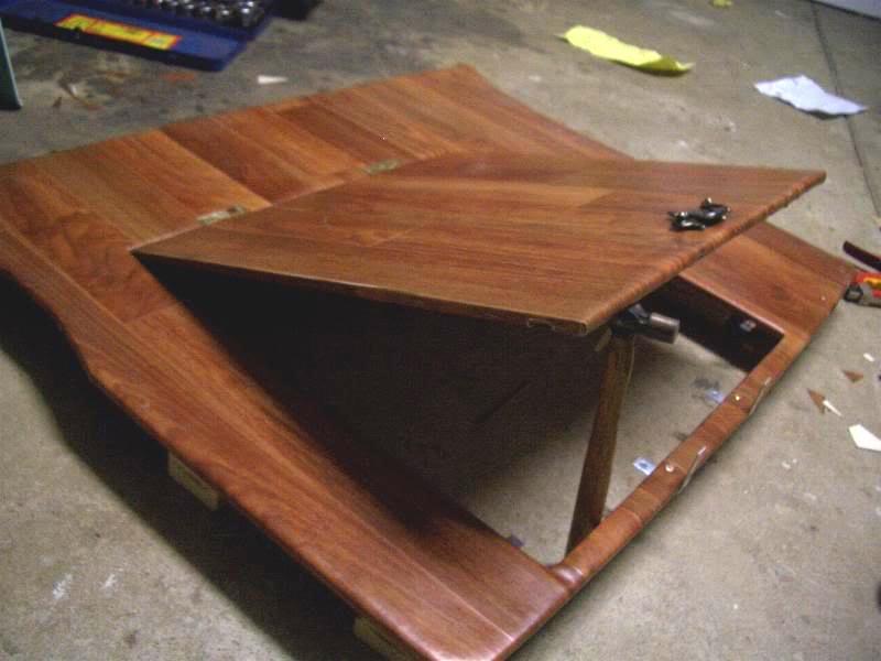
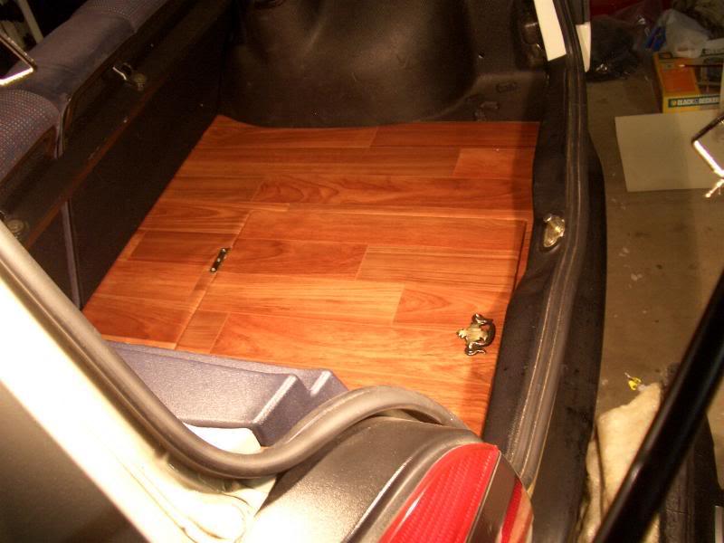
A trap-door was put in place to add to the different-ness as well. It was one of my favourite touches to this project
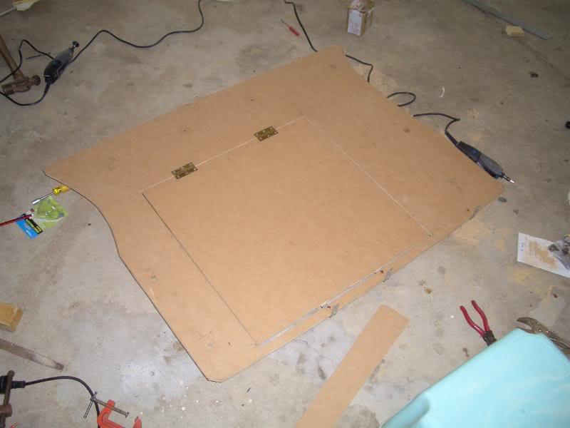
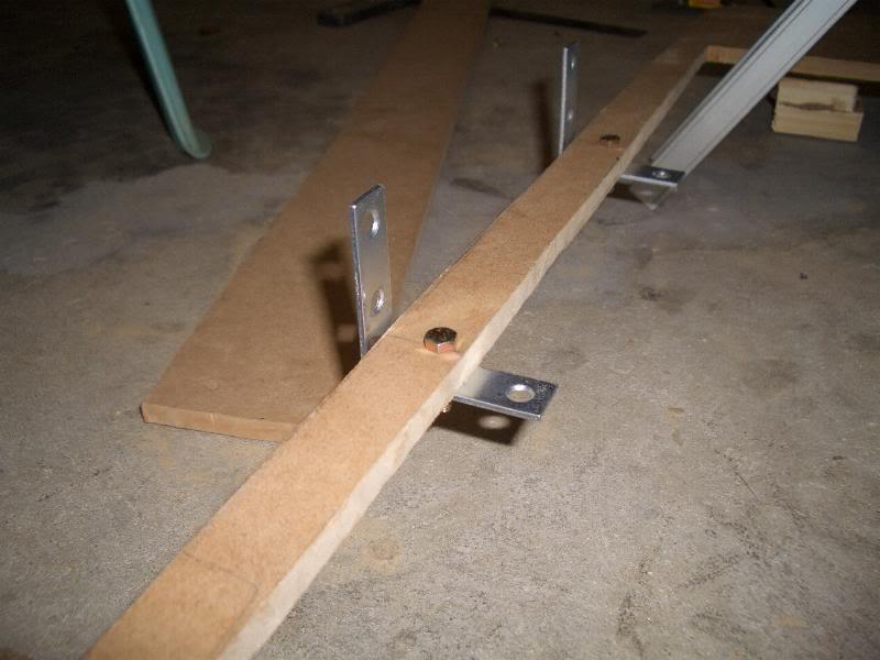
L brackets were used to stabilise the trap door, also doubling as a fastener so that it can be bolted to the body of the car so the floor wouldn't jiggle around. Small magnets were also added to the bottom of the trap door where it would rest on the L brackets to keep it in place while it's closed.
We liquid-nailed a few blocks of wood to have the false floor sit flush with the side pockets. While at Bunnings, we came across some vinyl flooring, and we couldn't ignore the faux timber boards they had! We just used liquid nails and a staple gun to hold the vinyl on, and while it looks dodgy, it did the trick. It was our first time at trying handiwork like this, so just cast a blind eye to the crappy side!
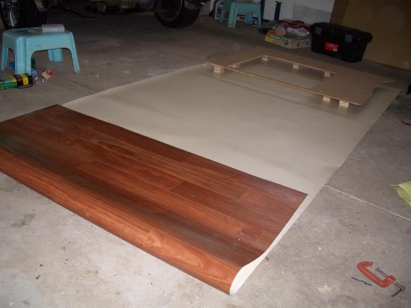
After a ton of staples:
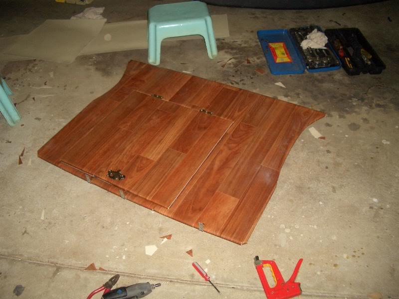
Oh yeahhh:
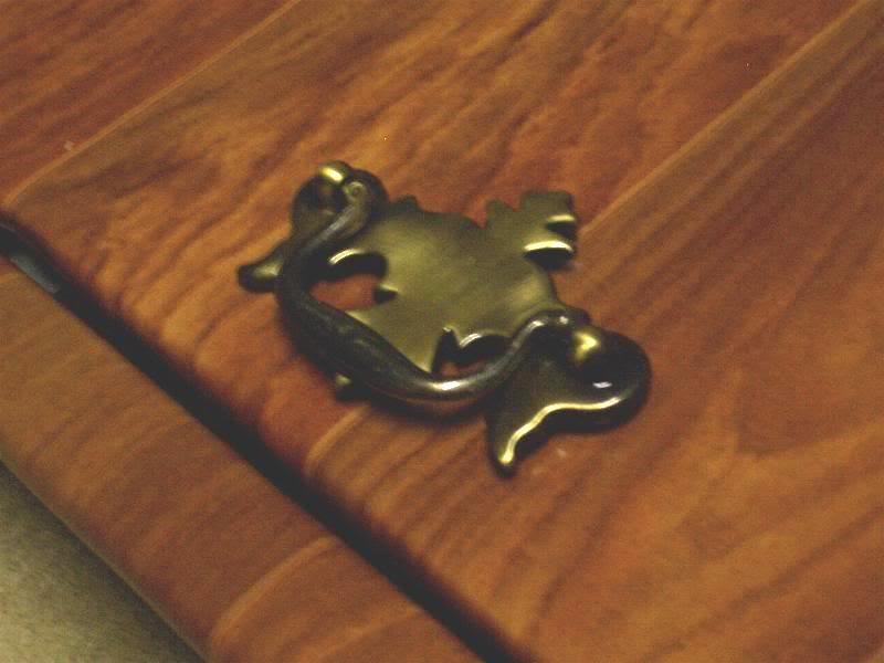
Found this at Bunnings and was too cool to pass up:
We started mucking around as the job was finally done:
 Last edited by rayray086; 21-01-2008, 07:21 PM.
Comment
-
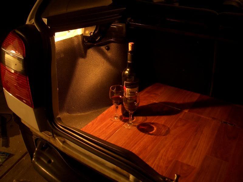
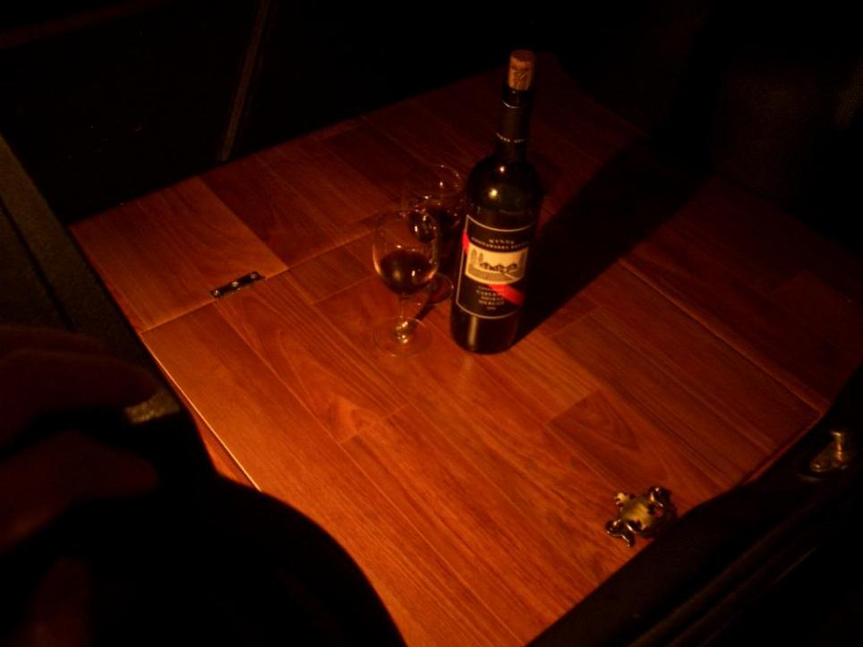
Some final pics of the false floor:
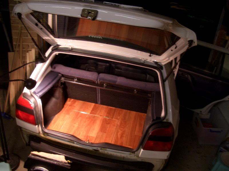
It was a job well done for my standards and we did a bit of celebrating
Comment
-
did you guys have a romantic drink after you finished??? HAHAHAHHAHAHAHAOriginally posted by rayray086 View PostComment
-
Battery relocation wasn't as fun as the false floor. Lots of trips to Jaycar was made as we kept changing plans and kept missing this and that. It was also frustrating to route all the cables around so they'd be secure and well insulated, trying to keep them as hidden as possible.
The battery was originally meant to go on the passenger side to take advantage of weight distribution, but because of the trap door, it wasn't physically possible. I also have a sub and amp going in soon and having the battery there would ruin a lot of our plans. So it was decided to mount it just behind the rear seats on the driver side.
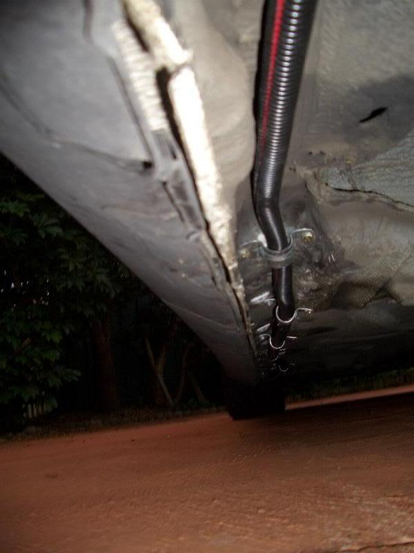
The main 2AWG cable from the positive post to the starter was routed down under the through the false floor, and then through the body into the rear passenger wheel well. Pipe brackets were used to hold the cables as close to the body as possible to avoid any rubbing, and is working very well so far.
The cable was then routed down under the side sills about 1 inch away from the jacking points. It sits under the jacking points too so any grounding out from driving over huge bumps shouldn't damage the cables in any way.
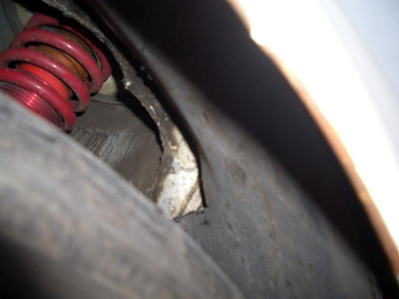
The cable was then routed up behind the plastic wheel guards in the front passenger side wheel well. I made a few cuts on these plastic guards to ensure the cable doesn't interfere with proper fitting of these guards
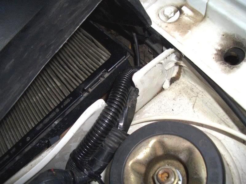
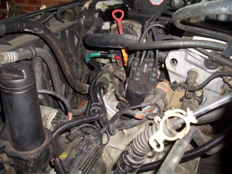
It's then routed through an already made hole that reaches under the rain tray (I'm assuming it's the same hole used by the side indicator wires) and then routed through to the engine bay by the same grommet used to route the ECU wires I believe:
From there, it follows the existing wiring to the starter motor. From the starter, a 4AWG cable connects up to a distribution block which runs two 8AWG cables that were originally connected directly to the positive post. I have no idea where they go to (if I had to guess, fusebox and ECU?) but the car starts and works exactly the same as before, so I'm not worried.
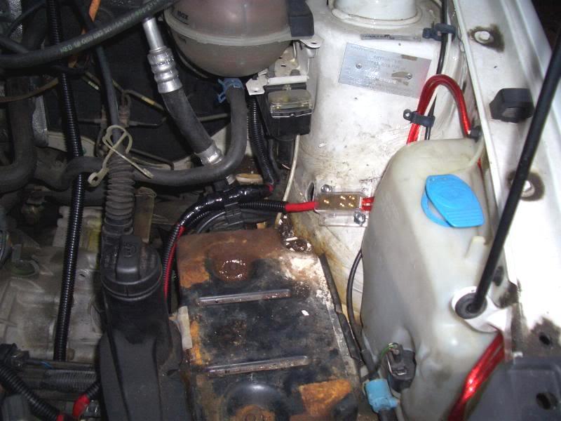
Another 4AWG links the starter to the alternator:
Comment
-
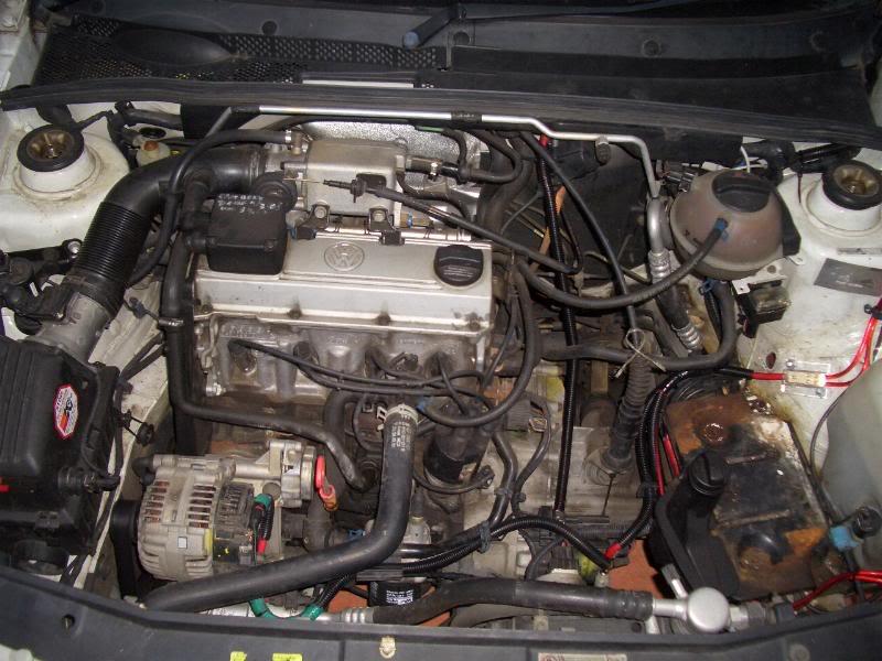
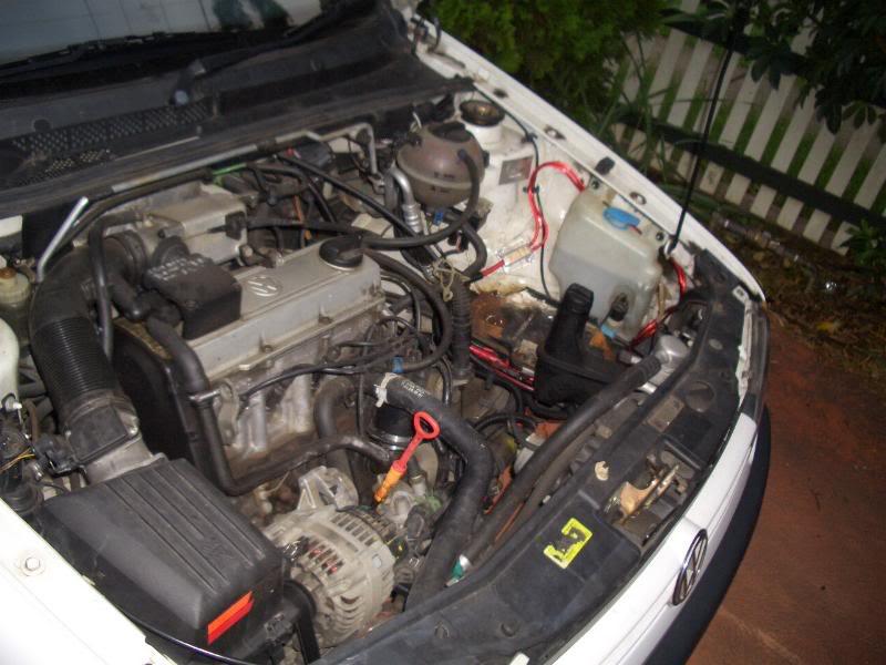
Some pics of the engine bay now:
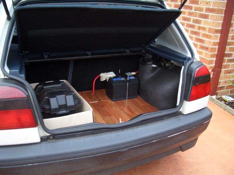
And another of the battery in the boot:
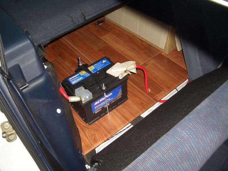
It started up fine the first time But my battery was low and went flat. It's now running a heavy duty ACDelco item that should last me another few years
I'll be redoing a few things in the near future to tidy up the setup, including improving the earthing and using a battery box/enclosure.Comment
-
Haha George, it was very intimate, but Louis is taken
Comment
-
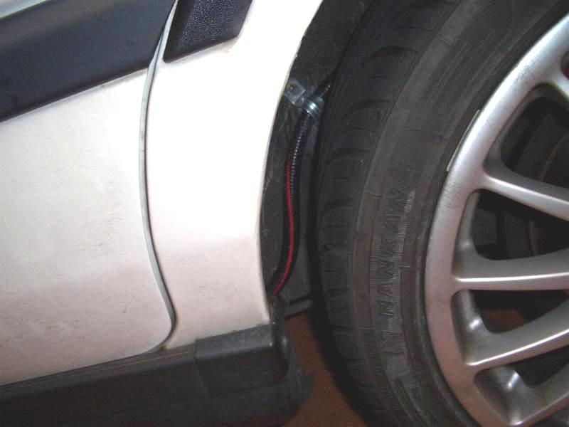
sorry ray,but that wire next to your rear tyre and on the side doesnt look safe... you sure thats not a defect?(not that im scared of a defect or two!)??? why didnt you pass it under your carpet just next to your transmission tunnel?Comment
-
I've made measures to keep it held tightly so it won't come loose, but you do have a point :S I've been reading around and most suggest to run it outside of the car, just as a safety issue if a freak fire was to erupt from any shorts. I guess I took this tip a bit too far and routed it outside of the car at the closest possible point... What do others think?Comment
Comment