G-8VXWWTRHPN Battery Control Module on Negative Lead - VWWatercooled Australia

Announcement

Collapse
1 of 2 < >

Email Notifications Failing (mostly Telstra)

Hello everyone. Seems there is an issue with Telstra (possible others) blocking email from our server. If you are trying to sign up I would suggest a different email if possible. If you're trying to reset your password and it fails please use the Contact Us page:
2 of 2 < >

Welcome to the new look VWWatercooled

After much work and little sleep there is a new version of the forums running on more powerful and recent hardware as well as an upgraded software platform.

Things are mostly the same, but some things are a little different. We will be learning together, so please post questions (and answers if you've worked things out) in the help thread.

The new forum software is an upgraded version of what came before, it's mostly the same but also a little different. Hopefully easier to use and more stable than before. We are learning together here, so please be patient. If you have questions, please post them here. If you have worked something out and can provide an answer,
See more
See less

Battery Control Module on Negative Lead

Collapse
X
 
  • Filter
  • Time
  • Show
Clear All
new posts

  • Battery Control Module on Negative Lead

    2011 Tiguan FWD, 2ltr Diesel.
    Hi
    Getting a error code for over voltage, Battery module is suspect, but how can I test it ?.
    Have removed plug to it and ran the engine, done a scan and the error is not showing, would that suggest the the Battery Control Module has a fault ?.


    "
    00447 - Function Limitation due to Over-Voltage
    001 - Upper Limit Exceeded - Intermittent
    Freeze Frame:
    Fault Status: 00100001
    Fault Priority: 6
    Fault Frequency: 1
    Reset counter: 83
    Mileage: 189907 km
    Time Indication: 0
    Date: 2063.14.31
    Time: 13:52:58


    Freeze Frame:
    Term 15 On
    Voltage: 14.85 V
    ON
    ON
    ON
    OFF
    OFF
    cheers
    Spike

  • #2
    @spike47: Hi.

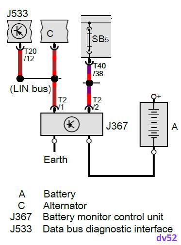
    First - let's look at the wiring diagram for the Battery Control Module on this car - which is called J367:


    As you can see - the 2 x pin connector on J367 connects the module to J533 and to a fuse. J533 is what a diagnostic device calls the (CAN) Gateway module - I suspect this is the module from which the SCAN snippet in your post was copied.

    Notice in my picture that I show the term "LIN bus". LIN is short for Local Interconnect Network - it's a low-speed, single-wire (as depicted in my diagram) communication protocol. In a LIN set-up there is a LIN master (in this case J533) and a number of LIN slaves (in this case the Alternator and J367).

    When you removed the 2 x pin connector from J367 (shown as T2 in my diagram) - surely the SCAN would have reported that J533 was no longer able to talk to J367?

    So, I can't answer your question because you have removed valuable data from your SCAN report and only posted a sub section of the diagnostic information. I'm not sure why folk keep doing this - maybe it's because they don't want to complicate their posts. However, there are many ways to read a SCAN report and the major advantage of a full report is that it gives the fault information context about the way that the ENTIRE car is built

    If you want to pursue this matter - post-up the FULL (meaning not edited) SCAN with the 2 x pin connector plugged into J367 (please). Again, don't edit ANY part of the report

    Don
    Last edited by DV52; 30-03-2024, 09:33 AM.
    Please don't PM to ask questions about coding, or vehicle repairs. The better place to deal with these matters is in the forum proper. That way you get the benefit of the wider expertise of other forum members! Thank you.

    Comment

    Working...
    X