 Tweet
Tweet
So the engine is done!! The bigger cam, exhaust header, valves, springs, lifters, rings etc all replaced and its sounding fine, very happy. However, with all this increased air flow I am finding it running a bit lean. After monitoring my wideband Air/Fuel meter over a series of drives I have noted my readings to be anywhere from 12-16, but more so around the 14.5-16 mark.
So what does this mean? For a reading of 14.7 (which is supposedly the optimum ratio for combustion and effiency) there are 14.7 parts air, to 1 part fuel. For performance you are most likely looking for something a little bit lower. From reading I have discovered that old school mustangs etc will run mixtures in the 10's, 11's and 12's, but I dont want anything that rich running through my 1.8l 8V!!!
Anyway Im running lean so its time to get those injectors working a bit harder and chip the Digilean. (Digifant)
The process is pretty straight foward.. (or so I thought) and I thought I would attempt a write up.
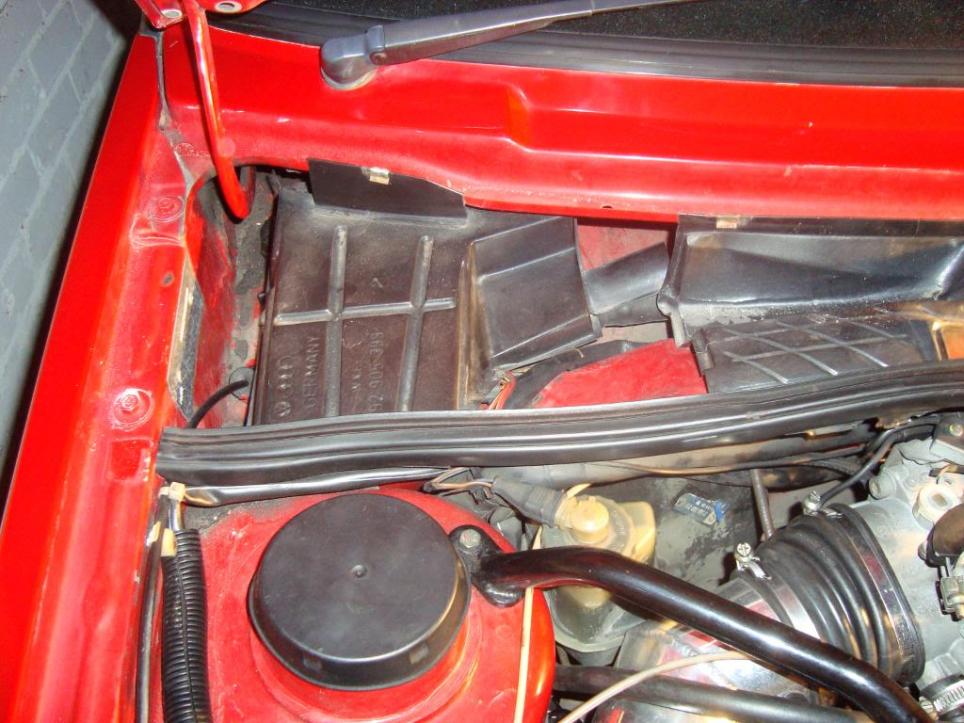
Stage 1 - Locate the ECU
In the top left hand corner underneath the rain tray is where the ECU is located. See below:
Stage 2 - Disconnect the battery, remove the rain tray, then remove the ECU.
Before we go any further it is important to disconnect the battery, both the postive AND negative terminals. We certainly dont want to damage the ECU!!
Next step, peel back the rubber seal on the front of the rain tray and gently pry the clips holding the piece covering the ECU up. Now you can remove this, exposing the ECU and ultimately giving you access.
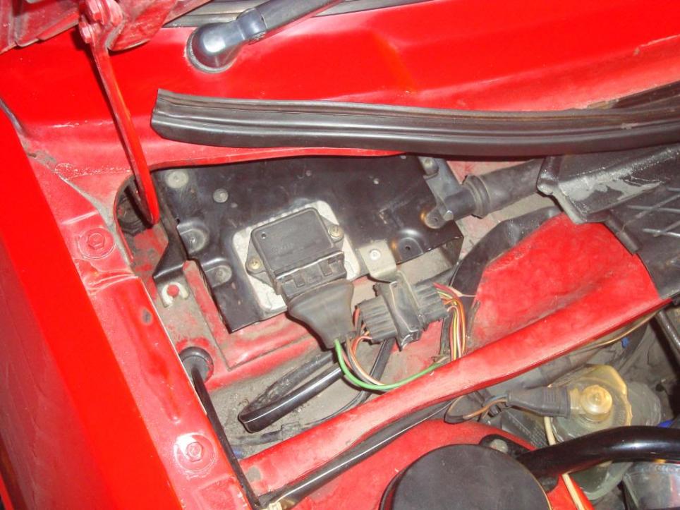
The ECU is held in place by a series of clips and one bolt. First thing is to disconnect the terminals, then get started on unscrewing that bolt which we can see below.
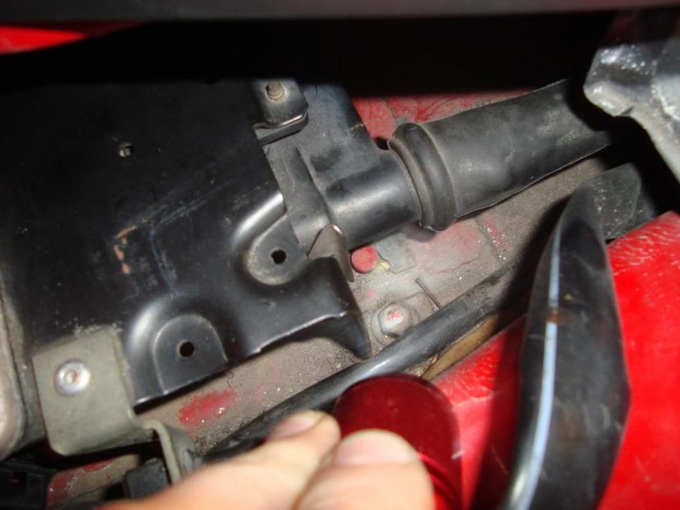
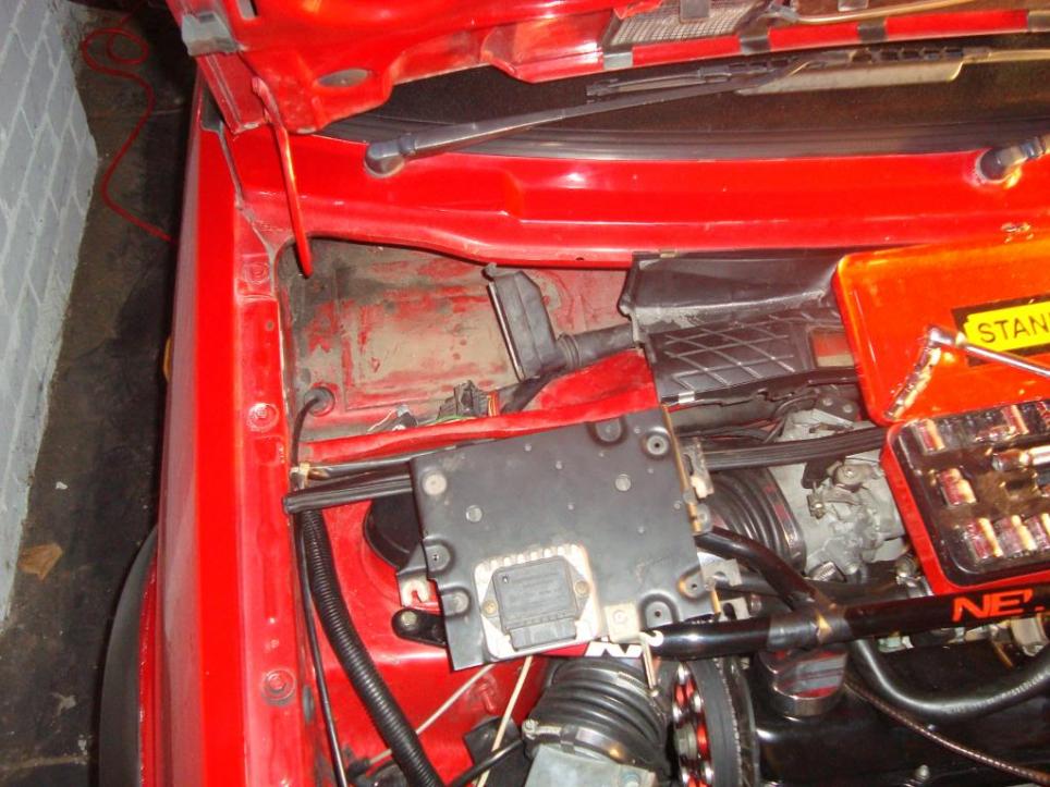
Once the bolt is removed it is just a series of clips holding the ECU in place. To unclip take a firm hold of the unit and push away from the engine bay (a small wiggle doesnt hurt) and it will come loose. We can see it removed below.
Stage 3 - Remove ECU casing and cover.
Now that its out of the car we can take it over to the bench and get started on opening it up. The case surrounding the unit is held in place with 3 very stubborn screws, we need to unscrew these first.
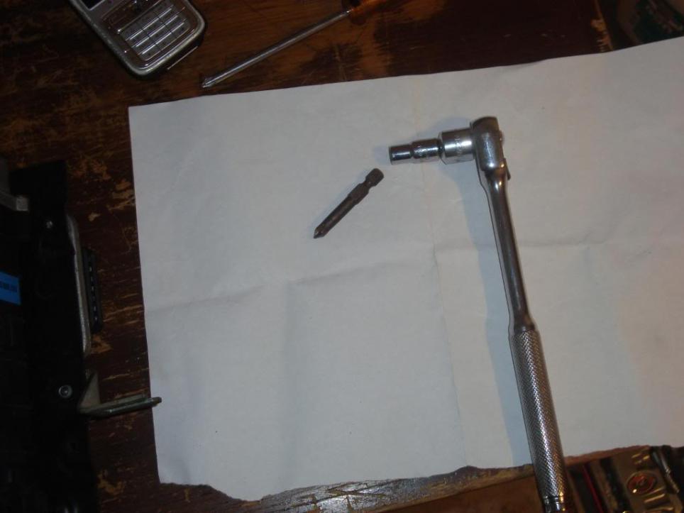
After struggling with a screw driver for awhile I fell back on the old trusty phillips head drill bit slotted into my wrench for a bit of extra leverage.
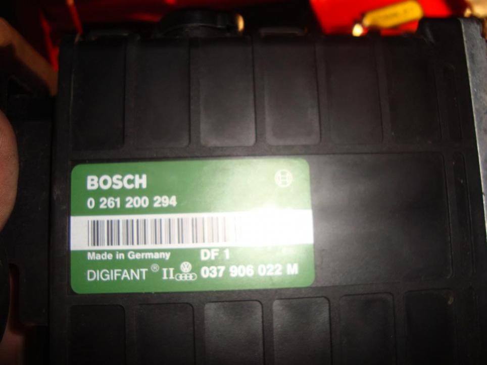
Now that the casing is off we can see the unit....
Now to take the cover off... At each end there are a series of screws, both of these must be unscrewed. Set of 3 on the black plastic end and 4 on the metal end from memory. Once these are off we can remove the case and expose the chip boards.
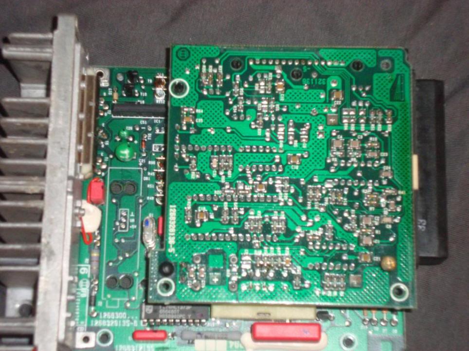
To get access to the chip we want to change we first need to unscrew to the two screws on the right hand side (you can see one on the top right is already done) and gently pull off two black plastic heads (you can see one on the top left is already done)se we can split the two boards.
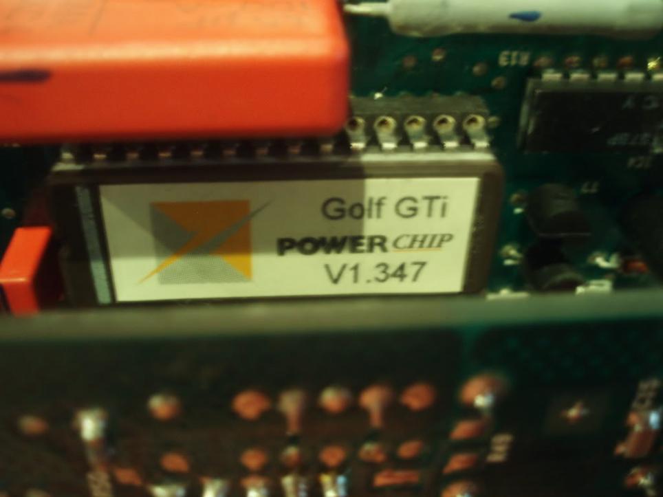
Now at this point I do not have more pics, upon opening everything up I discovered that my chip is in fact soldered into place. My understanding was some units have a chip terminal and some are soldered in, unfortunately mine is soldered in.
Rather than attempt to remove the chip and solder in the new one I have been advised to get down to Jaycar and get myself a terminal which i can plug the chip straight into. When soldering in a terminal as opposed to a chip you minimise any damage that you may do to the chip. The reason is; when they are soldered in originally, it is done by machine, thus the chips exposure to heat via the solder is minimal. In doing it by hand it is likely that you will be exposing the chip to excessive amounts of heat thus frying the inside!!
So the outcome... well I had to put everything back together, plug it all back in and now arrange a time to get down to Jaycar!!
Anyway stay tuned, for the remainder of this project. Any feedback, corrections ect would be appreciated.
Cheers.
So what does this mean? For a reading of 14.7 (which is supposedly the optimum ratio for combustion and effiency) there are 14.7 parts air, to 1 part fuel. For performance you are most likely looking for something a little bit lower. From reading I have discovered that old school mustangs etc will run mixtures in the 10's, 11's and 12's, but I dont want anything that rich running through my 1.8l 8V!!!
Anyway Im running lean so its time to get those injectors working a bit harder and chip the Digilean. (Digifant)
The process is pretty straight foward.. (or so I thought) and I thought I would attempt a write up.
Stage 1 - Locate the ECU
In the top left hand corner underneath the rain tray is where the ECU is located. See below:
Stage 2 - Disconnect the battery, remove the rain tray, then remove the ECU.
Before we go any further it is important to disconnect the battery, both the postive AND negative terminals. We certainly dont want to damage the ECU!!
Next step, peel back the rubber seal on the front of the rain tray and gently pry the clips holding the piece covering the ECU up. Now you can remove this, exposing the ECU and ultimately giving you access.
The ECU is held in place by a series of clips and one bolt. First thing is to disconnect the terminals, then get started on unscrewing that bolt which we can see below.
Once the bolt is removed it is just a series of clips holding the ECU in place. To unclip take a firm hold of the unit and push away from the engine bay (a small wiggle doesnt hurt) and it will come loose. We can see it removed below.
Stage 3 - Remove ECU casing and cover.
Now that its out of the car we can take it over to the bench and get started on opening it up. The case surrounding the unit is held in place with 3 very stubborn screws, we need to unscrew these first.
After struggling with a screw driver for awhile I fell back on the old trusty phillips head drill bit slotted into my wrench for a bit of extra leverage.
Now that the casing is off we can see the unit....
Now to take the cover off... At each end there are a series of screws, both of these must be unscrewed. Set of 3 on the black plastic end and 4 on the metal end from memory. Once these are off we can remove the case and expose the chip boards.
To get access to the chip we want to change we first need to unscrew to the two screws on the right hand side (you can see one on the top right is already done) and gently pull off two black plastic heads (you can see one on the top left is already done)se we can split the two boards.
Now at this point I do not have more pics, upon opening everything up I discovered that my chip is in fact soldered into place. My understanding was some units have a chip terminal and some are soldered in, unfortunately mine is soldered in.
Rather than attempt to remove the chip and solder in the new one I have been advised to get down to Jaycar and get myself a terminal which i can plug the chip straight into. When soldering in a terminal as opposed to a chip you minimise any damage that you may do to the chip. The reason is; when they are soldered in originally, it is done by machine, thus the chips exposure to heat via the solder is minimal. In doing it by hand it is likely that you will be exposing the chip to excessive amounts of heat thus frying the inside!!
So the outcome... well I had to put everything back together, plug it all back in and now arrange a time to get down to Jaycar!!
Anyway stay tuned, for the remainder of this project. Any feedback, corrections ect would be appreciated.
Cheers.

 HAHAHA
Comment