good thread!
I have pictures from my Octavia install, ill send them to you for this thread.
-
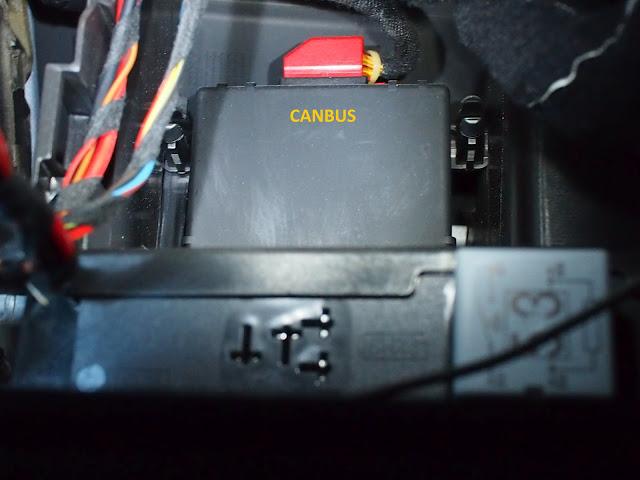
Don't mean to be pedantic, but the part is the 'CANbus gateway'. CANbus refers to the whole network of devices and cables in the car. Just to be accurate.Leave a comment:
-
Boost Pressure
This is where this whole thing started with me looking to get boost pressure displayed in the MFD.
There's a few options with how to display boost pressure - you can select units (mbar, bar, psi) and also where the data is sourced from (auto/infotainment/diagnostic).
Here's the full details on boost pressure - original post is here: INFO : Some detailed info about "TURBO PRESSURE" parameter (Read this before ask)
TURBO PRESSURE parameter (extended info)
How to configure you PolarFIS to correctly read turbo pressure
To read turbo pressure, normally it is not necessary to configure anything in your PolarFIS unit.
There is a configuration inside the box that automatically selects the best option to read turbo pressure.
However, there's a few models which this automatic function doesn't work.
This guide will help you to identify if this is your case.
These are available options in the turbo pressure menu:
- AUTOMATIC : PolarFIS will select the best option for your vehicle automatically. RECOMMENDED !! (by default)
- INFORT X1 : Obtain the turbo pressure from the infotainment bus.
- INFORT X2 : Obtain the turbo pressure from the infotainment bus. The reading is then multiplied by 2 (only vehicles in which the bus shows half pressure).
- DIAGNOSIS : Obtain the turbo pressure from the diagnosis bus, recommended in vehicles that the other options don't work.
What values does the PolarFIS show in my screen ?? I not have idea ...
The value that PolarFIS displays is the result of subtracting the barometric pressure from the boost pressure read from the bus.
This is due to the boost pressure sensor indicating values in absolute pressure (BOOST+BAROMETRIC)
But, sometimes i see negative values, why does this happen??
Normally with the engine at idle there will be a small vacuum in the intake manifold, so reading will be negative (around -5 to -15 mbar or -0.07 to -0.2 PSI). This is normal.
However, in some models there's no negative readings and with engine at idle the reading is 0 mbar or 0 PSI, we can't do anything about that because this reading is done directly from the Diagnostics bus of the engine ecu.
However, a small negative reading as indicated is normal, but if you have a reading less than -100 mbar or -1.4 PSI it means that boost is not reading correctly.
In this case, you must enter into the Polar FIS configuration menu, and select SCREEN->VISUALIZATION->ADVANCED->BOOST OPTIONS and choose the option INFORT. x2.
This is due to pressure read from infotainment bus being divided by 2 in some cars.
If the problem persists or you have no reading of boost pressure, enter in the same menu and choose DIAGNOSTICS option.Leave a comment:
-
Polar FIS+ Advanced, What is it ?
Advanced Polar FIS is the evolution of FIS + unit. It adds new parameters in addition to new features.
Polar FIS + enabled viewing vehicle parameters in the FIS screen, but Polar FIS Advanced, as well as incorporating more parameters, includes new features like the ability to modify the number of flashes of intermittent comfort indicators, function automatic lowering of the mirror on the passenger side when engaging reverse and some functions which are can only be activated with Diagnostic cable such as VCDS.
Which vehicles are compatible with Polar FIS+ Advanced
Same as Polar FIS +, are listed below:
- Volkswagen Golf V (1K)
- Volkswagen Jetta (1K)
- Volkswagen Caddy (2K)
- Volkswagen Tiguan (5N)
- Volkswagen Touran (1T)
- Volkswagen EOS (1F)
- Volkswagen Passat (3C)
- Volkswagen Scirocco (1K)
- Skoda Octavia (1Z)
- Seat Leon
- Seat Altea
What parameters can be displayed with Polar FIS+ Advanced ?
- Oil temperature (° C / ° F)
- Coolant temperature (° C / ° F)
- Outdoor temperature (° C / ° F)
- Fuel remaining (Litres / Gallons)
- Rpm motor
- Pressure turbo.
- Voltage of the battery.
- Atmospheric pressure
- Pressure fuel pump
- Motor load.
- Ambient Temperature (engine ECU)
- Coolant temperature engine output.
- Coolant temperature leaving the radiator.
- Mass air flow.
- Sensor 1 throttle pedal.
- Sensor 2 throttle pedal.
- Sensor 1 throttle valve.
- Sensor 2 throttle valve.
- Horse Power used cv.
- Oil level.
- Minimum oil.
- Brake master cylinder pressure.
- Pressure in the fuel rail.
- Torque used NM.
NOTE: Not all parameters are supported in all engine ECU, to know that data can be displayed, see the list of supported ECU: http://www.auto-polar.com/downloads/Supported_ECUs.xls
What is the role of intermittent comfort ?
The role of intermittent comfort, allows you to select the number of intermittent flashes that the comfort indicator makes. Standard, with one touch gives 3 flashes intermittently with Polar FIS Advanced, select up to 10 flashes.
You can also cancel additional flashes by pressing the indicator comfort again, for example, if you have set the indicator at 10 flashes on comfort, it will flash with a short press on the control 10 flashes, unless pressed again to cancel.
What is the function of mirrors down ?
Advanced Polar FIS can be configured to engage on selection of the reverse gear for the passenger mirror to dip down automatically to a preset position. There are 2 modes: Manual and Automatic.
In manual the mirror will lower only if the passenger position “L” is selected.
In automatic, the mirror will be lowered only when the car is parked with the indicator directed towards the space.
NOTE: Due to construction features of vehicles it cannot be guaranteed that mirror position will be "perfect". On models equipped with this function from factory the mirror incorporate a position sensor, which does not happen with those without park assist mirrors, so the mirror will function in the same way, but can not be guaranteed to position "millimeter perfect".
What diagnostic functions are available ?
- Modification of the sensitivity of the rain sensor.
- Modification of the sensitivity of the light sensor.
- Enable / Disable American DLR.
- Enabling / Disabling daytime running lights.
- Enabling / Disabling cornering fog lights.
- Enabling / Disabling second rear fog light (where bulb exists).
- Enable / disable automatic closing from 15 km / h.
- Enable / disable rain closing.
- Enabling / Disabling one touch closing windows.
- Enable / Disable hazard warning in case of sharp braking.
NOTE: These functions, Polar Advanced FIS performs are via coding of the ECU with the requested function, so if this function is not supported by your vehicle ECU, then it cannot be activated.
What are the other features of the Polar FIS+ Advanced ?
- Built in VIM to enable video on stereo screen while vehicle is in motion.
- POLAR Advanced FIS supports OEM bluetooth and Fiscon bluetooth, unlike other products, POLAR Advanced FIS does not use the Bluetooth menu in the FIS, but creates a new menu called Advanced POLAR FIS.
- The name of the created menu is customisable, which can substitute the name POLAR Advanced FIS by the text you want (up to 10 characters)
- Option to turn off the POLAR Advanced FIS screen off making the unit undetectable when taking the car in for service or repair. Is reactivated by simply pressing the OK button on the steering wheel or windshield wiper lever for 10 seconds.
- Automatic temperature units (° C, ° F), Speed (kmh / mph) and Size (Litres / Gallons) selected in the FIS.
- Manual selection of the units in which you want to display the parameters relating to pressure. Automatic, mbar, bar, PSI.
- Multi-function steering wheel / Wiper stalk control.
The keys can be set from within the FIS POLAR Advanced menu do the following.
Modify volume.
Changing audio track.
Change the parameters displayed in the bottom of the screen line POLAR FIS +.
You can also configure the keys inside the AUDIO menu do the following.
Modify volume.
Change audio track (useful for cars in which the multifunction steering wheel is not installed at the factory and these keys do not work).
IMPORTANT: FOR CARS THAT ARE NOT EQUIPPED MULTIFUNCTION STEERING WHEEL, THE OPTION OF CHANGING AUDIO TRACK IS NOT AVAILABLE.
KEY FEATURES OF THE WHEEL IS NOT AVAILABLE IN ALL THE VEHICLES, since it depends on the vehicle configuration.
- Polar Advanced FIS automatically installs itself in the gateway, so you do not need diagnostic software after installation
- Updates via the Internet, via our website: Autopolar Official Web site
- New aluminum frame.Last edited by tigger73; 16-12-2012, 10:11 PM.Leave a comment:
-
List of Additional Functions
Complete list of all functions available
Nº
Name
Description1 TVFree_function TV-Free function to see video in motion 2 Battery_drain Battery drain fix for vehicles equipped with RNS-510 and old gateways before index "K" 3 Parktronic emulation Parktronic OPS emulation function (see Parktronic screen in RNS510 with Parktronic PDC ecu) (only available with Skoda vehicles) 4 Blink function Comfort blinkers configurable from 3 to 10 blinks 5 Mirror function Mirror lowering function (passenger mirror goes down to a configured position when engage reverse gear) 6 BT_compatibility (White_DOT) Add BT Hands free compatibility with White dot Hands free units (Can works with all models of BT for white dot cars up to this date) 7 RNS-510_hidden_menu Activation / deactivation of RNS-510 hidden menu 8 Diag 1 DIAG : 1 - Adjust sensibility percentage automatic wiper 9 Diag 2 DIAG : 2 - Adjust sensibility percentage automatic lights 10 Diag 3 DIAG : 3 - Activation/Deact. Daytime running lights 11 Diag 4 DIAG : 4 - Activation/Deact. cornering lights 12 Diag 5 DIAG : 5 - Activation/Deact. american lights 13 Diag 6 DIAG : 6 - Activation/Deact. cornering lights 14 Diag 7 DIAG : 7 - Activation/Deact. warning lights (blinkers) 15 Diag 8 DIAG : 8 - Activation/Deact. of second rear fog light 16 Diag 9 DIAG : 9 - Activation/Deact. windows automatic rain closing 17 Diag 10 DIAG : 10 - Activation/Deact. automatic closing at 20 Kmh 18 Diag 11 DIAG : 11 - Activation/Deact. one touch closing Last edited by tigger73; 16-12-2012, 09:30 PM.Leave a comment:
-
Mirror Dipping Feature - Setup
Mirror Dipping Feature - Setup
OK here's a short video off my phone showing set-up of mirror dipping feature on AutoPolar FIS+ Advanced.
The key thing that I think a lot of people get wrong is selecting the mirror positions before selecting either manual or auto. If the mirror dipping is set "OFF" then selecting the positions has no effect. First select "manual" or "auto" and second step is to set the "normal/driving" and "parking/reversing" positions.
"Manual" mode setting requires the mirror selector switch to be set to "R" and reverse gear to be selected for the passenger mirror to dip to the selected position.
"Auto" mode will dip the mirror irrespective of the mirror selector switch, however the car must be in reverse with indicator lights on.
If you don't have mirror dipping as a standard feature you may find that the mirror does not return to exactly the correct position. If this is the case you can use the adjustment menu and select + or - amount as an offset the the return position.
I got this working for the passenger side mirror, but found I had to swap to select drivers mirror on the selector knob to get dipping on the left mirror after restarting the car. I think this is a special RHD "feature" that may get fixed in a future firmware release.
There's also a function to get both mirrors working at the same time - if you select right both will move, but if you select left then only left moves. That's one of the other options in the mirror menu (Alt. mode).
Mirror dipping is not supported on both mirrors at the same time as the drivers mirror is not connected to the ECU - only passenger mirror. Hence only passenger mirror can be controlled via command to the ECU.Last edited by tigger73; 17-12-2012, 07:06 AM.Leave a comment:
-
Parameter List
Complete list of all parameters available
Nº
Name
Description1 VELOCIDAD Real Speed extracted from ECU motor 2 TEMP_EXT External Temperature 3 RPM RPM Engine 4 V_BAT Battery Voltage 5 FUEL_LIT Petrol Tank Litres 6 TEMP_OIL_CAL Calculated Oil Temperature 7 TEMP_OIL_ACT Measured Oil Temperature 8 TEMP_AMB Engine Ambient Temperature 9 TEMP_INTAKE Intake Air Temperature 10 TEMP_COOL Cooler Temperature 11 TEMP_ENG_OUT Engine Coolant Output Temperature 12 TEMP_RAD_OUT Radiator Coolant Output Temperature 13 TEMP_FUEL Fuel Temperature 14 PRES_BOOST_SPE Request Boost Presure 15 PRES_BOOST_ACT Measured Boost Pressure 16 PRES_ATMOS Atmospheric Pressure 17 IMAP Intake Manifold Absolute Pressure 18 PRES_FUEL_SPE Required Fuel Pump Pressure 19 PRES_FUEL_ACT Measured Fuel Pump Pressure 20 PRES_FUEL_RAIL Fuel Rail Pressure 21 PRES_BRAKE Brake Pedal Pressure 22 PRES_BRAKE_BOOST Brake Pump Pressure 23 LOAD_CAL Calculated Engine Load 24 LOAD_ACT Measured Engine Load 25 MAF1 Mass Air Flow 26 MAF2 Mass Air Flow 27 ACC_PEDAL_1 Acelerator Pedal Position 28 ACC_PEDAL_2 Acelerator Pedal Position 29 ACC_VALVE_1 Acelerator Valve Position 30 ACC_VALVE_2 Acelerator Valve Position 31 TORQUE Engine Torque 32 POTENCIA Engine Power (HP) 33 OIL_LEVEL Oil Level 34 OIL_MIN_LEVEL Oil Minimun Level 35 INJ_TIMING Injection Timing 36 IGN_ANGLE Ignition Angle 37 MIS_SUM Misfire Sum 38 MIS_1 Misfire Cylinder 1 39 MIS_2 Misfire Cylinder 2 40 MIS_3 Misfire Cylinder 3 41 MIS_4 Misfire Cylinder 4 42 MIS_5 Misfire Cylinder 5 43 MIS_6 Misfire Cylinder 6 44 MIS_7 Misfire Cylinder 7 45 MIS_8 Misfire Cylinder 8 46 MIS_9 Misfire Cylinder 9 47 MIS_10 Misfire Cylinder 10 48 MIS_11 Misfire Cylinder 11 49 MIS_12 Misfire Cylinder 12 50 MIS_X1000_1 Misfire Cylinder 1 51 MIS_X1000_2 Misfire Cylinder 2 52 MIS_X1000_3 Misfire Cylinder 3 53 MIS_X1000_4 Misfire Cylinder 4 54 MIS_X1000_5 Misfire Cylinder 5 55 MIS_X1000_6 Misfire Cylinder 6 56 MIS_X1000_7 Misfire Cylinder 7 57 MIS_X1000_8 Misfire Cylinder 8 58 MIS_X1000_9 Misfire Cylinder 9 59 MIS_X1000_10 Misfire Cylinder 10 60 MIS_X1000_11 Misfire Cylinder 11 61 MIS_X1000_12 Misfire Cylinder 12 62 AD_1 Angle Delay Cylinder 1 63 AD_2 Angle Delay Cylinder 2 64 AD_3 Angle Delay Cylinder 3 65 AD_4 Angle Delay Cylinder 4 66 AD_5 Angle Delay Cylinder 5 67 AD_6 Angle Delay Cylinder 6 68 AD_7 Angle Delay Cylinder 7 69 AD_8 Angle Delay Cylinder 8 70 AD_9 Angle Delay Cylinder 9 71 AD_10 Angle Delay Cylinder 10 72 AD_11 Angle Delay Cylinder 11 73 AD_12 Angle Delay Cylinder 12 74 TEMP_EXHA_1 Exhaust Temperature 75 TEMP_EXHA_2 Exhaust Temperature 76 TEMP_E_CAT Catalyzer Input Temperature 77 AFR_LAMBDA_1 AIR/FUEL Ratio (LAMBDA 1) 78 AFR_LAMBDA_2 AIR/FUEL Ratio (LAMBDA 2) 79 FUEL_TRIM_1_3 Fuel Trim Bank 1/3 80 FUEL_TRIM_2_4 Fuel Trim Bank 2/4 81 N75_SPE N75 Duty Cycle Specified 82 N75_ACT N75 Duty Cycle Actual 83 INJ_QTY Injection Quantity 84 INJ_START Injection Start 85 INJ_DUR Injection Duration 86 INJ_START_QTY Injection Start Quantity 87 INJ_QTY_1 (D.1 m/str) Injection Quantity 1 88 INJ_QTY_2 (D.2 m/str) Injection Quantity 2 89 INJ_QTY_3 (D.3 m/str) Injection Quantity 3 90 INJ_QTY_4 (D.4 m/str) Injection Quantity 4 91 INJ_QTY_5 (D.5 m/str) Injection Quantity 5 92 INJ_QTY_6 (D.6 m/str) Injection Quantity 6 93 INJ_QTY_7 (D.7 m/str) Injection Quantity 7 94 INJ_QTY_8 (D.8 m/str) Injection Quantity 8 95 INJ_QTY_9 (D.9 m/str) Injection Quantity 9 96 INJ_QTY_10 (D.10 m/str) Injection Quantity 10 97 INJ_QTY_11 (D.11 m/str) Injection Quantity 11 98 INJ_QTY_12 (D.12 m/str) Injection Quantity 12 99 EGR_1 EGR Duty Cycle, EGR 1 100 EGR_2 EGR Duty Cycle, EGR 2 101 CHAR_PRES_CTR_SPE Charge Pressure Control Specified 102 CHAR_PRES_CTR_ACT Charge Pressure Control Actual 103 TEMP_PRE_TURBO Temperature Prior Boost 104 DPF_TEMP_1 DPF Temperature, DPF 1 105 DPF_TEMP_2 DPF Temperature, DPF 2 106 DPF_VOL_1 DPF Oil Ash Volume, DPF 1 107 DPF_VOL_2 DPF Oil Ash Volume, DPF 2 108 DPF_LLENADO DPF Filling 109 DPF_CONT_REG DPF Regeneration Counter 110 TEMP_E_DPF DPF Input Temperature 111 TEMP_S_DPF DPF Output Temperature 112 LATERAL_G G Lateral Force Last edited by tigger73; 16-12-2012, 09:27 PM.Leave a comment:
-
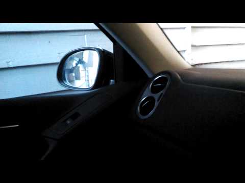
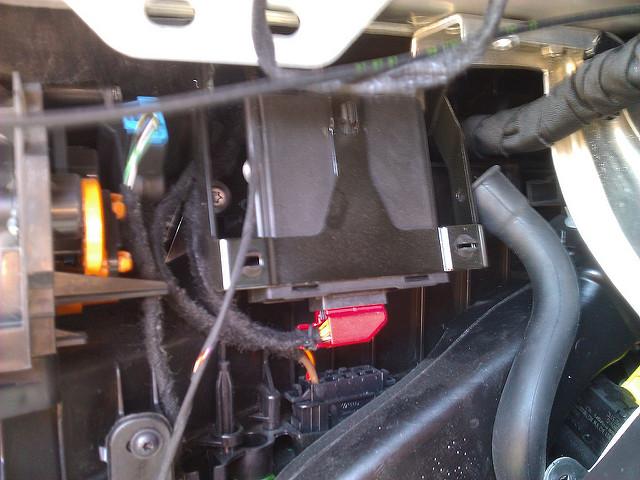
Golf Mk V Installation
Location of CANBUS gateway in MY 07 MK5 Golf 2.0L TDI (courtesy of Transporter)
Originally posted by TransporterLast edited by tigger73; 18-12-2012, 01:20 PM.Leave a comment:
-
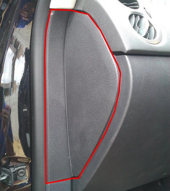
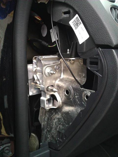
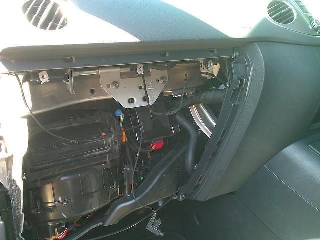
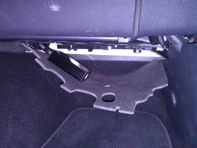
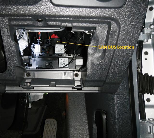
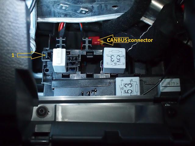
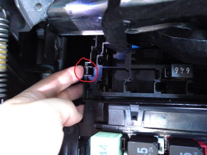
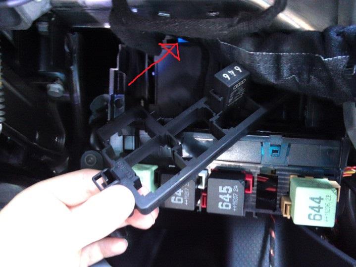
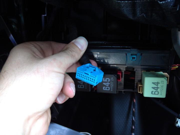
Tiguan
Installation of FIS+ in Tiguan
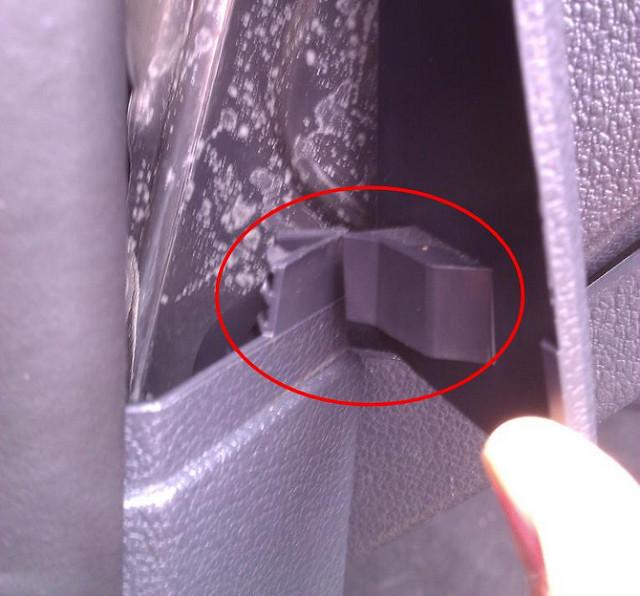
OK after much searching I've finally located the CANBUS gateway in my Tiguan. It's in behind the glove box - requires removal of the glovebox and it is very simple install once this is removed.
Glovebox removal instructions (thanks to bambazonke):
1. Remove 5 torx screws (3 at top and 2 at the bottom)
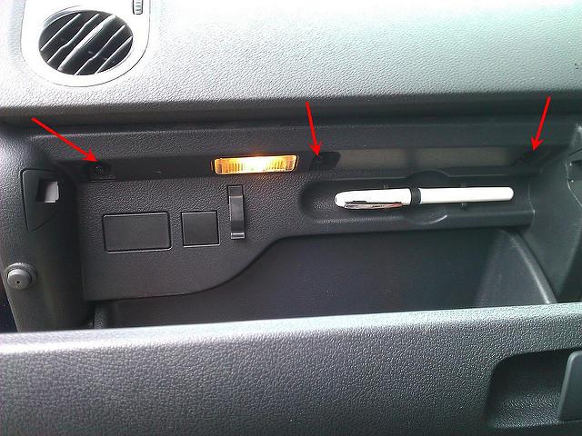
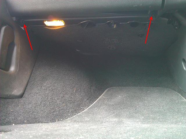
2. Unclip side panel by wedging upwards and then pulling out from rubber door seal
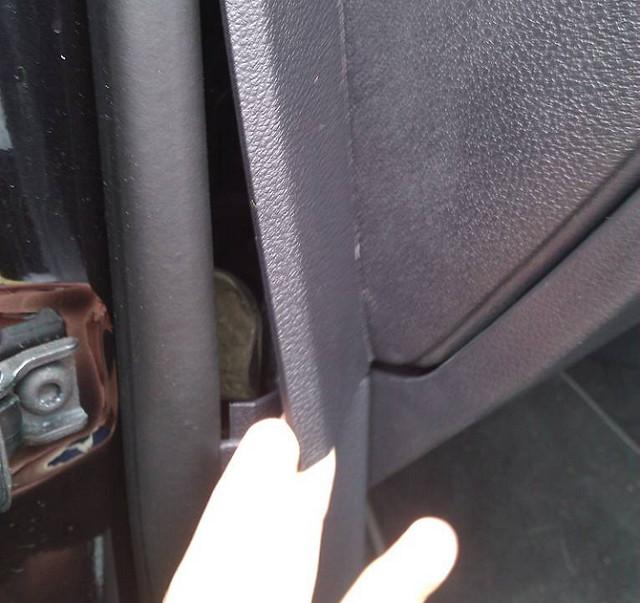
3. Wedge carefully out cubby hole light and unplug
4. Slide glove box out and then unclip rubber tube from air con to cool glove box
5. Unclip glove box light switch from the back of the glove box near the air con tube as discussed in step 4
6. Unclip open/close contact switch from centre back of glove box housing
Then you'll see that gateway connector right in front of you:
7. Assembly is in reverse order.
I've stashed the Autopolar FIS+ box just under the removable trim in the footwell so there's only a wing nut to undo and easy access to the unit for future firmware upgrades.
 Last edited by tigger73; 16-12-2012, 10:47 PM.
Leave a comment:
Leave a comment: