If this is your first visit, be sure to
check out the FAQ by clicking the
link above. You may have to register
before you can post: click the register link above to proceed, registering will remove the in post advertisements. To start viewing messages,
select the forum that you want to visit from the selection below.
This means you should apply for your renewal now to avoid any disruptions to your membership whilst the renewal process is taking place! NOTE: If you have an auto renewing subscription this will happen automatically.
Thanks, Tim
Will look for that position when I get home this evening. Do you also mean you extend the hard plastic line with fuel line, not shut it off?
Sid
thats the one. We just nip the factory ends off and re-use them onto the flexible fuel hose. At the end of the day that way you can relocate the canister anywhere you want on the car as you dont need frequent access to it.
Thanks again. Seems the way to go. My can will arrive this week (THANKS, GREG (best ever service provider!)) and I look forward to a weekend of fiddling.
Sid
Not trying to jump all over Gregs suggestions/solutions. Just trying to share my take on the situation. S0 yeah have a look and see what you think yourself.
Btw once youre under there you will find there is no bracket to mount on. The easiest solution is a couple of large good quality cable ties. (not $2 shop specials) You could go to the trouble of fabricating a nice bracket if it made you feel better but there would be no real benefit. Its out of sight anyways.
It is certainly a good location for it. I always used the cavities like that when fitting additional bypass filters not only to commercial vehicles but to cars as well. Always making my own brackets.
Jump in all you want Tim, I believe in co-op-itition rather than competition, especially with businesses that are customer focused, price competitive and know what they are on about. Plus I'm the first to admit I don't know everything!!
I link quite a few customers to your website products actually, and I recently decided not to bring in the BFI stuff as you are already doing it, and I aim to specialize in the emission, fabrication and diesel side of things. You should be proud of the business you run, and just your pricing alone tells me you are about the customer, not huge profit, and that speaks volumes to me.
You are very welcome anytime and your knowledge is an asset to the community.
I am however very jealous of your active signature banner....
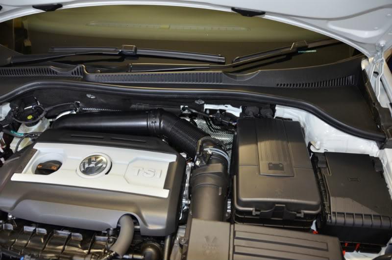
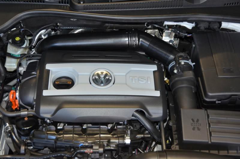
They are mainly used on the GTI/R as these "FSI" engines have been catered directly for by the aftermarket manufacturers. You can fit a catch can to anything really, and all you need to do is work out the blowby outlet, the return inlet, and plumb the can in between. Eventually there will be kits for all the models, but this is a huge task, and is taking a lot of time. Anyone half handy could easily fit one, and a pic of your engine from the top helps no end in sorting mounting and plumbing out!
2014 Skoda Yeti TDI Outdoor 4x4 | Audi Q3 CFGC repower | Darkside tune and Race Cams | Darkside dump pDPF | Wagner Comp IC | Snow Water Meth | Bilstein B6 H&R springs | Rays Homura 2x7 18 x 8" 255 Potenza Sports | Golf R subframe | Superpro sways and bushings | 034 engine mounts | MK6 GTI brakes |
Most thanks to Greg at carformance (Carformance | Performance Car Parts | Volkswagen Audi Car Parts | Diesel Performance | Aftermarket mods) who is an example to suppliers, johnvw for his advice and 42DD for their product. Thanks to many other who have posted on this subject as well.
Because this post is picture intensive, it will, unfortunately, be divided into a number of sub-posts. Sorry!
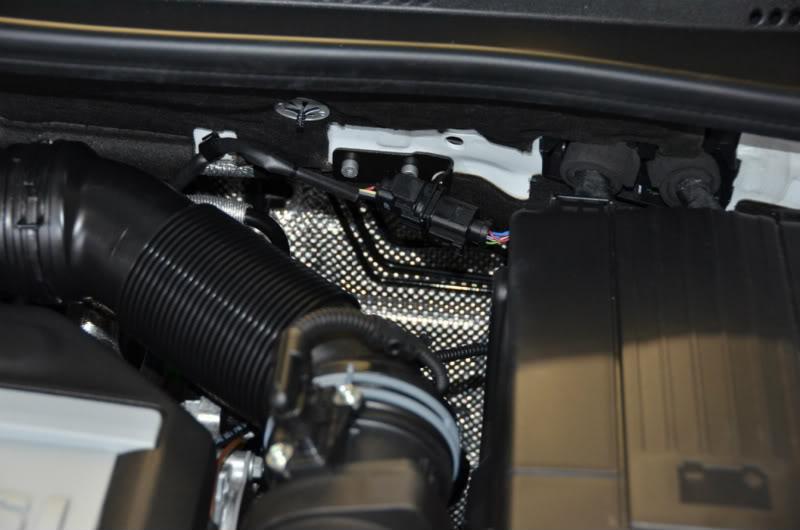
Those of us with new GTI’s might be disappointed that we cannot ‘bolt in’ the beautiful 42DD catch can with the same ease that our R companions are able to. However, the need to tinker a bit more with the install process suited me just fine. Firstly 42DD don’t have a plate yet to bypass the PCV valve, secondly the return line from the catch can is less easily installed and thirdly the easily accessible position to fit the can behind the passenger light is not available, nor is the position behind the driver’s light (unless the carbon canister is moved (thanks Tim) or a new bracket is made (as per johnvw)). I overcame the positioning problem by installing the can against the firewall in a position where an electrical connector is fitted as standard.
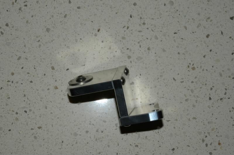
I adapted the bracket supplied by Greg for the R install slightly.
I used two parts of the three piece bracket and cut and bent a third piece. This allows the can to hang vertically (the firewall is not vertical), moves the can forward slightly to allow easy access to the dipstick and drops it a little lower (to allow unhindered replacement of the electrical connector).
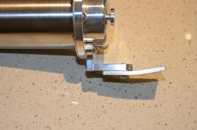
As the can is not as accessible as if it were behind one of the lights, I do recommend a drain tap (again, from Greg) and hose from the can to a suitable draining point under the car.
Now, the plumbing. I had on hand conventional 19mm ID heater hose (which will perish after a while when exposed to the oil flowing through it) and also 19mm ID hydraulic hose from Enzed (hose code 611-12).
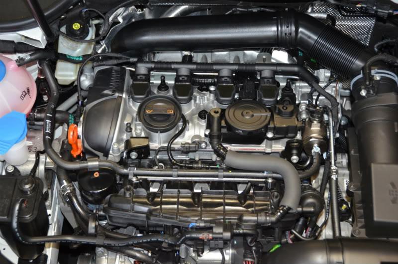
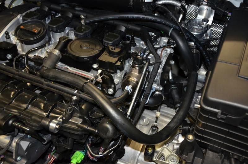
Firstly remove the engine cover (pulls upwards off four mounting posts easily – pull up on each corner).
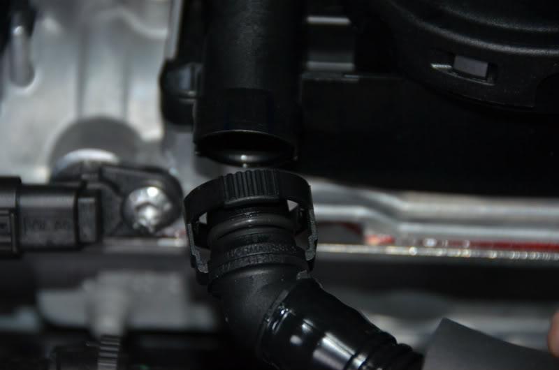
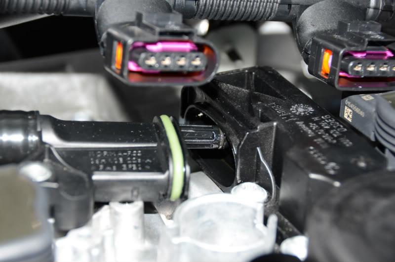
Next, remove the PCV to intake manifold hose. This is attached by connectors which are disconnected by pressing in on the knurled ring at their ends
Plug off the intake manifold inlet using the intake manifold inlet plug (supplied by Greg)
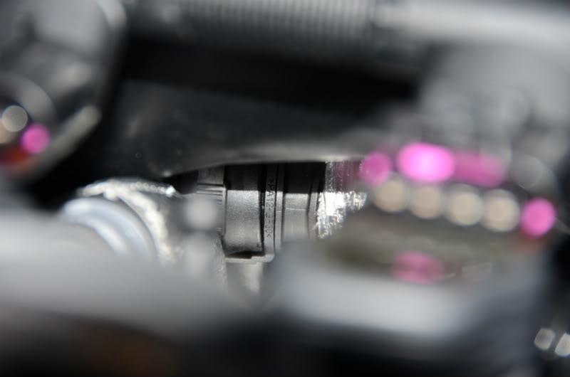
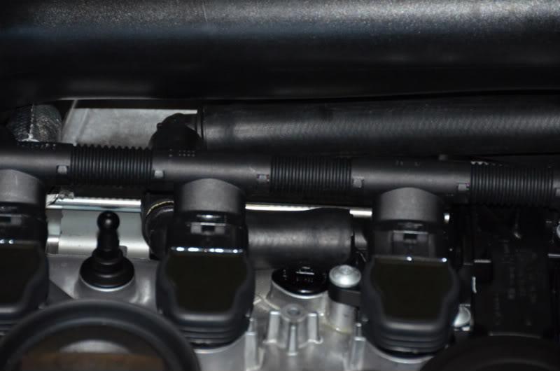
Disconnect the corrugated hose that runs from the back of the camcover plate to the large air intake pipe. That hose is attached to the air intake pipe using the same quick-connect attachment as is used on the hose from the PCV valve. Once you are actually fiddling inside the engine bay, these things become much easier to understand.
It is a bit of a bugger to get to that connector, but I was able to by passing one hand under the air-intake pipe and pressing backward on one side of the knurled ring, and passing my other hand over the back and pressing forward on the other side of the knurled ring.
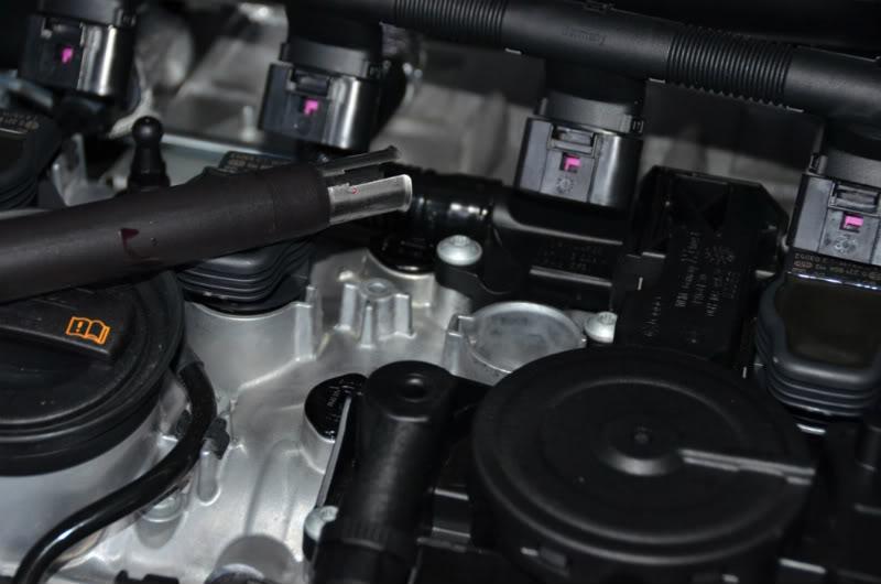
Once the connector is released from the air-intake pipe, I’d suggest disconnecting the spark plug cables,
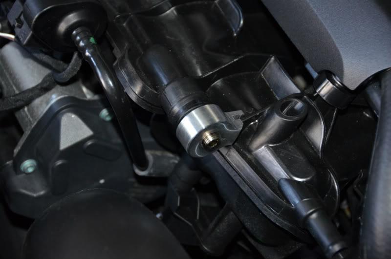
remove the coil from the third spark plug,
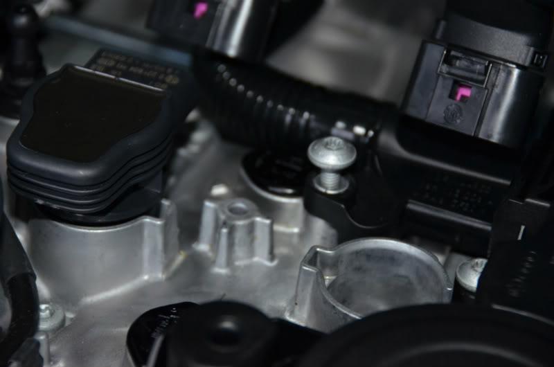
and then unscrew the torx screw holding the part of the cam cover plate to which the corrugated hose is attached
and remove that with the hose still attached
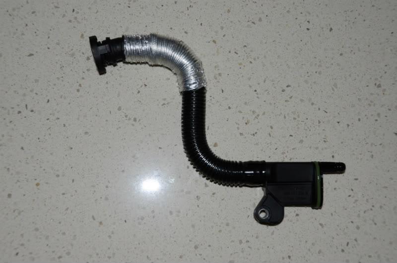
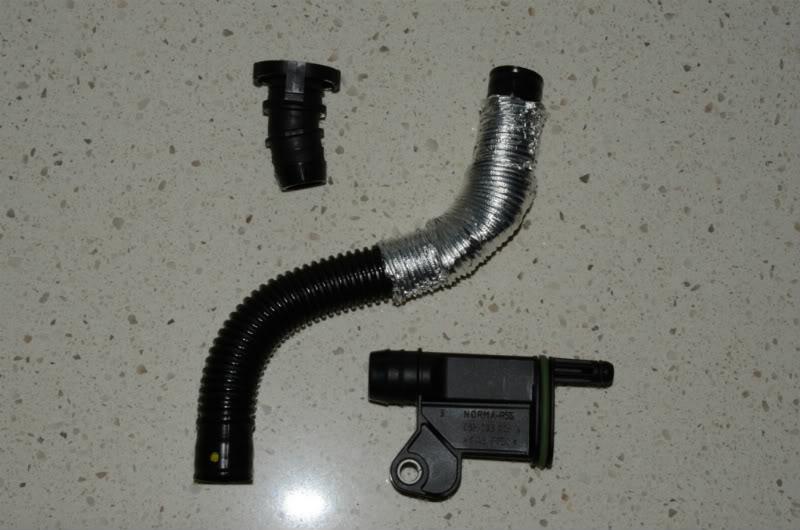
Remove the corrugated hose off both the quick connector and off the cam cover plate outlet by leaving the end of the hose with the connectors in a mug of boiling water – that allows you to easily pull the hose off the connector.
Make up a new hose to run from the catch can to the air intake tube. 19mm heater hose (or 611-12 hydraulic hose from Enzed - what I used) snugly fits over the quick release connector. This will connect to the top connector on the catch can.
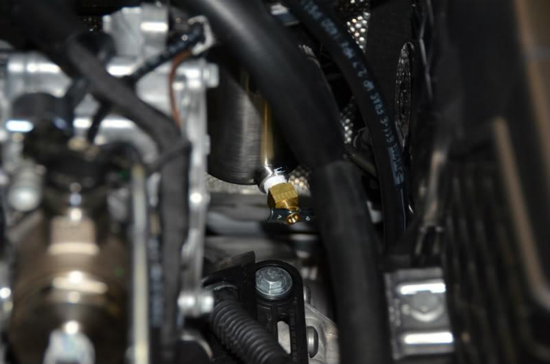
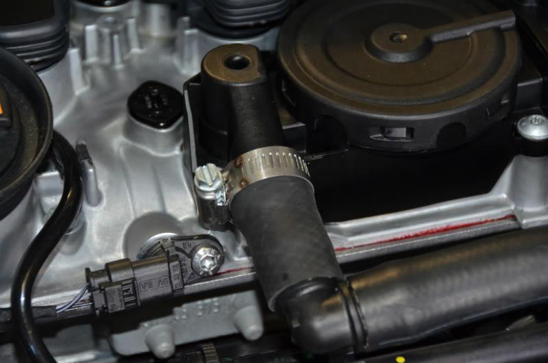
I had two options to replace the front corrugated PCV to inlet manifold pipe with a newly fabricated pipe to go to the catch can. I was able to get a piece of 19mm ID heater hose (I couldn’t, however, get the 611-12 hydraulic hose to stretch enough) directly onto the outlet of the PCV valve. Be careful if you do this – replacing the PCV assembly would be rather expensive, I’d imagine! I then clamped it in place.
An alternative would be to sacrifice the PCV to inlet manifold hose as I did with the rear hose - remove the corrugated tube off the quick release connector that was attached to the PCV valve (another mug of boiling water) and fit your choice of hose over the connector – I didn’t do it that way firstly because I didn’t want to destroy that hose and secondly, the diameter of this connector is less than the diameter of the connector which runs from the back of the PCV cover - I wasn’t sure how well it would fit inside my choice of hose. Route the hose toward the right of the engine and then back toward the catch can. In the picture above you will see I used 90 degree bends (from Greg – you will understand now how helpful he is!) to allow me to replace my engine cover with the setup looking as OEM as possible. Others have dremeled out a new ‘cutout’ in the engine cover and others just leave off the cover.
The hose along the right side of the engine needs to be made up before you fit it as it needs a ‘T’ connecter to collect a hose which runs from the back of the camcover plate (on which the PCV valve is installed).
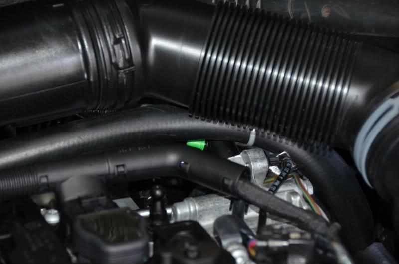
Once this is done, firstly connect the hose from the top outlet on the catch can and plug the other end back into the air intake pipe. Fortunately this is much easier than removing it!
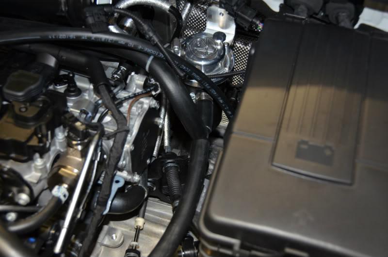
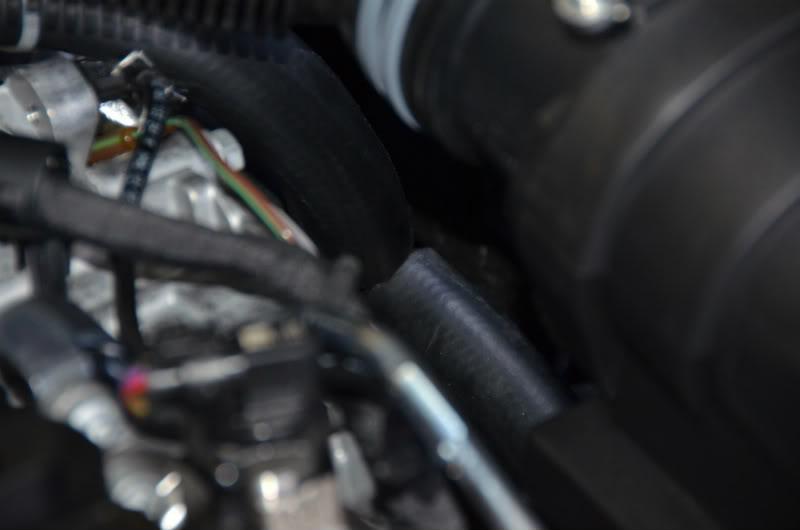
Next, connect the intake hose to the catch can. That hose is made up of the hose from the PCV valve, routed along the right side of the engine with a T junction inserted just before it reaches the catch can (in the picture above). Joining that T junction is a hose from the rear cam cover outlet which runs from that outlet to the right just behind the spark plug wiring, and underneath the big air tube. This picture shows the hose already in place.
It then descends down to join the ‘T’ junction. (The ‘T’ is inserted upside down in the hose on the right of the engine).
Reinstall the connector to the cam cover plate, replace the spark plug coil and wiring.
Replace the engine cover.
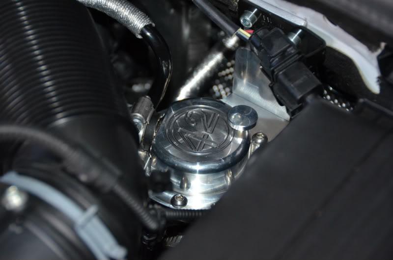
Here’s the catch can in position
And here is the finished product!
Now collect all the crud into the can that normally goes into your intake manifold.
Enjoy!
Sid
I was just thinking where to mount the can earlier this evening and thought the space near the battery and above the ABS unit could be a solution.. and you've cracked it!!
Mitsubishi Pajero Sport - Super Select 2WD/4WD Toyota 86 GTS Performance Pack Moon Slate - RWD MINI Cooper S Clubman - FWD
 Tweet
Tweet


Comment