Above Forum Ad

Collapse

Announcement

Collapse
No announcement yet.

VW 2.0litre 16v cutaway pictures.

Collapse
X
 
  • Filter
  • Time
  • Show
Clear All
new posts

  • VW 2.0litre 16v cutaway pictures.

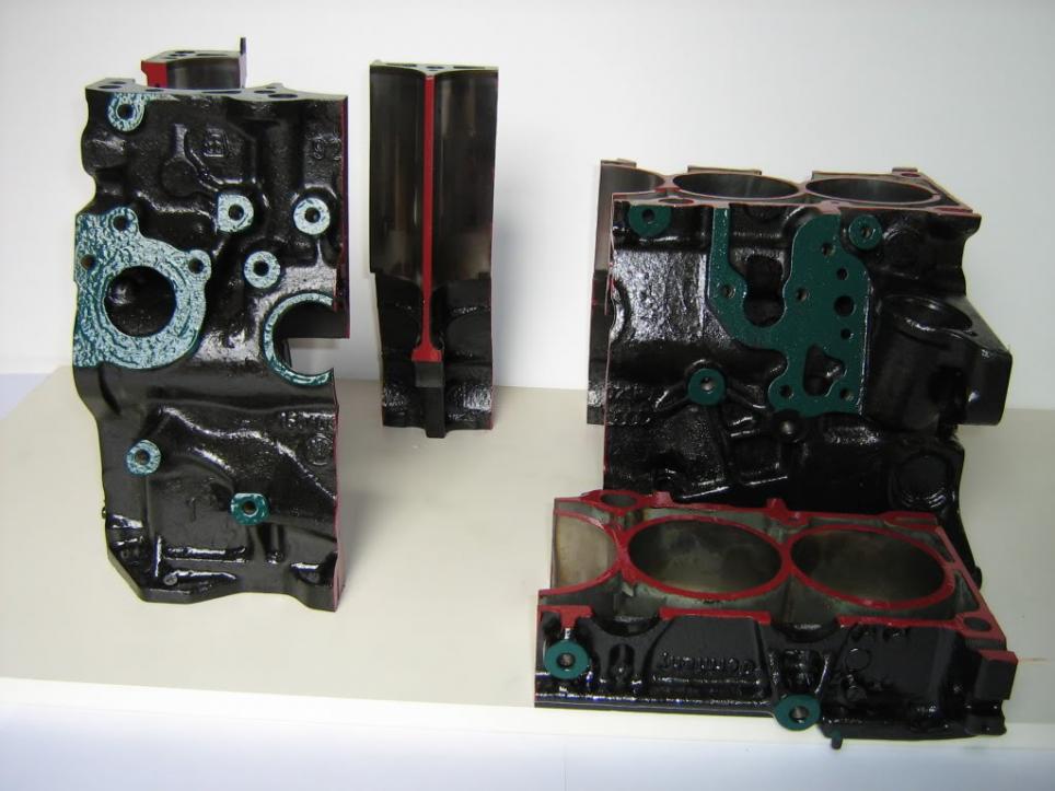
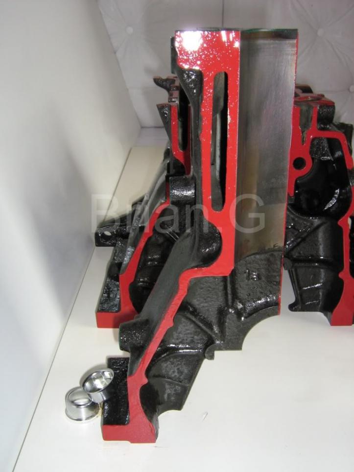
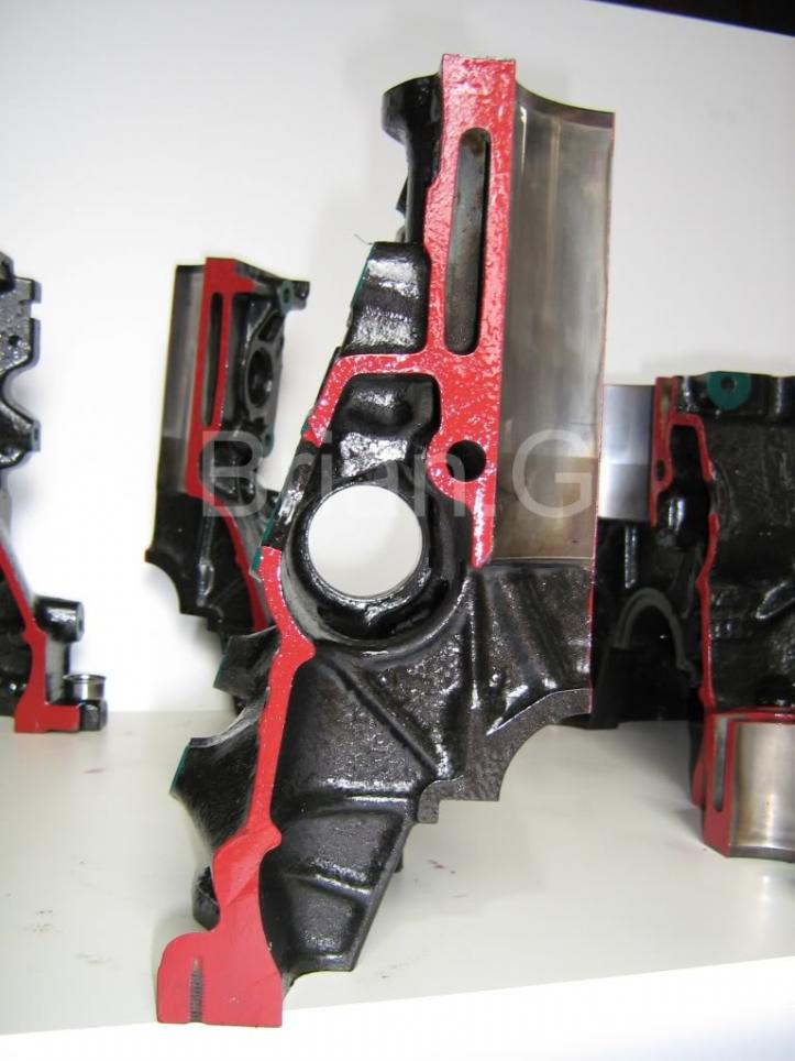
    Done for the future reference of all engine gurus worldwide.
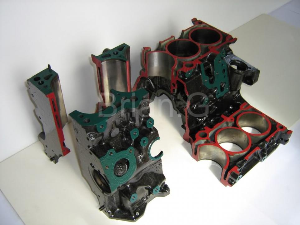
    Should answer all questions in respect to how far out the 2.0l block can be taken to.

    Here we go now, enjoy!

    Engine code 6A.


  • #2


    Green surfaces are VW factory faces, red surfaces are my own cut surface ground faces.
    And the all important measurements>
    Bore 82.50mm
    Stroke 92.80mm
    Average wall thickness of block through out(non high load areas)> 6.00mm.
    Distance between bores taken with a high quality vernier callipers> 5.72mm.
    Average main oil way gallery's diameter> 12.30mm.
    Oil feed to head, average diameter> 5.60mm.
    Distance from bore wall to root of oil squirter thread> 3.20mm. (''root measurement'' as in root of the thread of banjo bolt that holds squirter in place)
    Minimum bore wall thickness> 4.44mm, max 7.80mm.
    Average deck thickness, pretty uniform throughout>minimum measurement> 16.00mm
    Bridge piece across water passage at number 1 and 4 cylinder> 10mm high x 17mm wide.
    Block featured is a standard bore 2.0L 16v 6A external water pump forged crank(this had one?) type block with approx 150k miles.
    I hope these pictures and specs help everyone who is thinking of or in the process of building a great engine.
    I also hope these pictures will put peoples minds at ease with any doubts they may be having when it comes to boring these babies out or planing the deck, tapping oilways for remote supplies, dry sumping,etc.

    Points to note are>
    The bridge across water passage which is not in the 1.8T block as seen in this section too.
    The mould bridge stabiliser seen between the 2 cylinders, fitted at time of casting to aid stability to cores im sure.
    The general beefiness of the entire block compared to the AUG 1.8T.
    Casting is solid between main bearing carrier and base of bore.
    I stand by all of the above measurements.

    Comment


    • #3
      Wow!

      Thankyou.

      Pete
      79 MK1 Golf Wreck to Race / 79 MK1 Golf The Red Thread / 76 MK1 Golf Kamei Race Car
      7? MK1 Caddy
      79 B1 Passat Dasher Project
      12 Amarok

      Comment


      • #4
        Thats some great pics and info their , well done.
        sigpic
        Mk2 GTI 2 door 1.9l 8v turbo 1st mk2 1st engineered water vw nats 09
        Mk1 twin eng twin turb
        scirocco gti 2.1l 16v turb 6spd
        Audi A4 B5 1.8t

        Comment


        • #5
          Man, you have to be careful with angle grinders in the garage. They can do some real damage!

          Gavin
          Last edited by h100vw; 21-06-2009, 09:38 PM.
          optimumcode@gmail.com | https://www.vwwatercooled.com.au/for...i-;-79012.html | https://www.facebook.com/TTY-Euro-107982291992533

          Comment


          • #6
            Originally posted by Brian.G View Post
            The mould bridge stabiliser seen between the 2 cylinders, fitted at time of casting to aid stability to cores im sure.
            This is called a chaplet, it fuses to the molten iron in the casting process if all goes right. Yes, it is to stop core shift as the liquid metal flows through the mold.

            great piccies and info Brian, Can you tell more of the story why this came about, must be a good hand grenaded engine somewhere for you to get to this point !!
            Lots of MK 1 Scirocco's...

            If it aint a MK 1 then it must be a donor car ??

            Cheers,
            Grant...

            Comment


            • #7
              It came about really from a long history working with VWs and how to pull the most hp from them.
              Ive had many VW engines and have build plenty too including the 16vg60.
              These pictures/idea above came into play for my new engine build, a 16v n/a engine.
              I plan to take the very most i can out of this engine to get what i want so these cutaways were the most thing i needed to see whats what in there and what sizes stuff is in there.
              So this weekend I did the above and go all the info i needed, posting to share that info with everyone who shares the same great curse as I do
              I have also posted the full set of head cutaway pictures in this section too.

              Comment


              • #8
                Excellent work mate. Thanks!

                APR Tuned | KW Suspension | INA Engineering | Mocal Oil Control |
                Website: http://www.tprengineering.com
                Email: chris@tprengineering.com

                Comment


                • #9
                  Glad you like it

                  Comment


                  • #10
                    Brilliant bit of work

                    Thanks for all the hard work.
                    I joined this forum as a result, great to see this kind of contribution to the knowledge base for all of us to learn.
                    I am thinking about possibly adding squirters to an old ME block if it does not have them already (waiting for the block to show up next week). I have read elsewhere that it might have the holes but are capped off, I have not been able to confirm this.
                    Seeing your cutaway images helps me understand what I need to do to accomplish this if I have to drill and tap the block.

                    Anyone any comments on cutting notches at the top of the curve on the rod bearing, a number of folks seem to do this mod to improve cooling of the piston in absence of squirters.

                    Thanks again Brian G.
                    Grumman Kubvan, 1.6L TD
                    sigpic
                    Exploring the Salish Sea

                    Comment


                    • #11
                      Its no problem, glad they helped you, if you want ANYMORE pictures or dimensions just let me know and ill post them up for you. I can also re-cut the pieces if an area you need to see isent displayed above.

                      Re the notches, it can be done no problem, only a small nick is needed, it lets the excess run off from the shells spit up onto the underside of the piston crown.
                      Be exact with the amount of material you remove to keep them all the same, maybe make a jig or something.
                      Polish the nick after to insure it doesent foul the crank shoulders/thrust face.
                      Good luck and have fun!

                      Gimme a shout if you need to know anything else, Brian Garvey.

                      Comment


                      • #12
                        squirter cross section

                        A cross section of the squirters port running up into the main oil feed channel would be cool.

                        You might find this cross section of the injectors and the associated discussion interesting.


                        Thanks for the additional advice on the crank squirters.

                        Peter
                        Grumman Kubvan, 1.6L TD
                        sigpic
                        Exploring the Salish Sea

                        Comment


                        • #13
                          Originally posted by 49thdiver View Post
                          A cross section of the squirters port running up into the main oil feed channel would be cool.

                          You might find this cross section of the injectors and the associated discussion interesting.


                          Thanks for the additional advice on the crank squirters.

                          Peter
                          Ok pete, do you mean cross section of the feed running upto head? Or a cross section of the oilsquirter ,or a section through parallel along main oil gallery?

                          Comment


                          • #14
                            Thanks! Awesome Pic.
                            500 x 100 max size on sig pics please!!

                            Comment


                            • #15
                              Oil squirters

                              Thanks Brian,

                              A cross section view looking from the end of the block, ie down the oil gallery. Showing the oil squirter port drilled into the flat spot on the underside of the bore. ie where the oil squirter t's into the oil gallery.
                              see sketch attached.


                              After re-reading your post I realize that you have suggested a cross section of the squirter parallel to the oil gallery, this would be interesting also, however probably more difficult to cut as I suspect the the tube is at an angel to the main axis of the block, as I have portrayed in my crude sketch.

                              I picked up the ME block today and it has neither oil squirters or capped off ports, so I will be attempting to drill this ports out.

                              Thanks again for the great work, and interest in my project.

                              Peter
                              Last edited by 49thdiver; 11-08-2009, 03:10 PM. Reason: second thoughts on post
                              Grumman Kubvan, 1.6L TD
                              sigpic
                              Exploring the Salish Sea

                              Comment

                              Working...
                              X